Distribution box wiring diagram. Connecting wires in a junction box - everything is possible if you know the rules. Various ways to connect switches and lighting fixtures
Hello, dear readers and guests of the Electrician's Notes website.
Due to the increasing demand for installation of electrical wiring without junction boxes, I increasingly began to be asked questions about the wiring diagram for switches with this design.
With sockets, everything is simple here - the power cable is connected directly to the terminals of the socket, and from it, if necessary, further sockets are connected. This connection is called a “loop”.
Connecting sockets with a cable is not prohibited; the main thing is to comply with a number of requirements of the PUE for connecting a PE conductor, but I will tell you about this in my next article. If you don’t want to miss new releases, then subscribe to the site’s newsletter.

Well, today I will tell you using visual examples about connecting switches without junction boxes.
According to many citizens, distribution boxes interfere with and spoil the external design of a renovated apartment or house. Of course, because who wants to see a lot of plastic caps on expensive wallpaper!? Therefore, each of the customers wants to hide these boxes out of sight as much as possible, thereby forgetting the most important requirement of the PUE that the wire connection points must always be accessible for inspection and repair.

Let's consider several options for implementing hidden junction boxes.
The first option is to install distribution boxes on the ceiling behind the tension fabric.


If a malfunction suddenly occurs, the suspended ceiling can always be removed, the necessary work carried out and installed back. But sometimes a fault cannot be found and detected immediately, or it has crept into more than one room. Then you will have to remove the ceilings in the entire apartment.
For example, in our country, removing a ceiling in one room costs about 1,000 rubles. So do the math! To remove and install a suspended ceiling, for example, in three rooms will cost about 6,000 rubles. Not a cheap pleasure...
The second option is a little better, but it is usually used if the ceiling is made of plasterboard. It consists of making special inspection hatches in the ceiling, through which access to the distribution boxes is provided. The hatch is usually placed somewhere in the corner of the room and, naturally, all distribution boxes should also be installed in the location of the hatch.

In principle, this option can also be used for suspended ceilings, but how to implement such a hatch in a suspended ceiling?! The answer to this question was not even given to me by the relevant specialists, which is why I had to install it in one of the apartments in the corner behind a suspended ceiling without any inspection hatches.

The third option is to install electrical wiring without junction boxes.
This is what we’ll talk about today in more detail.
Let's start with the fact that electrical wiring without junction boxes certainly has its advantages.
1. No unnecessary wire connections
The logic is simple: the fewer different kinds of connections, the more reliable the network. Poorly made connections of wire cores in addition to incorrectly selected ratings of protection devices can lead to poor contact, heating and ultimately to an open circuit or short circuit.

Unobstructed access to the wire connection point. The socket or switch mechanism is removed and access is open.

3. Reducing the cost of electrical installations
Using this method certainly reduces the cost of electrical installation work, because the number of installed points and the number of disconnected cores becomes much smaller.
The disadvantages of installing electrical wiring without distribution boxes include only some excess cable consumption during installation.
Having analyzed all the advantages and disadvantages of this method, let’s move directly to the switch connection diagrams.

In my example, the electrical wiring in the apartment is made without distribution boxes, so the power cable, in this case VVGng (3x1.5), from the apartment panel goes directly into the socket box of the single-key switch. This, by the way, is the same bathroom, about.
The second cable in the socket box is the outgoing line for lighting, which is also made with VVGng cable (3x1.5).

have a depth of 45 (mm), so installing a touch switch with a depth of 33 (mm) there and laying all the wires is quite problematic, but it is possible! Yes, by the way, ordinary single-key switches have much smaller dimensions, so there will most likely be no problems with their installation.
For clarity, I am attaching a wiring diagram for connecting a single-key switch without a junction box.
Let me remind you what the familiar one looks like.
But we will look at the diagram for connecting it, but only without a junction box.
Here everything is similar to the previous scheme with a single-key switch, only instead of one lighting group, two are used.
Thus, now we have not two cables in the socket box, but three. One cable is the power cable from the apartment panel, the second is a cable to one lighting group, and the third is to another lighting group or a fan, as in my example.
I will show you the connection diagram on the same switch from Livolo, just imagine that it is not single-sensor, but dual-sensor. Its external design is exactly the same, only the internal circuit has been changed and another terminal L2 (Load) has been added.
We connect the incoming phase from the apartment switchboard to the common terminal L(In) of the two-sensor switch, to terminal L1(Load) we connect the switching phase of the outgoing lighting cable, and to terminal L2(Load) - the switching phase of the outgoing cable of the exhaust fan. We connect the neutrals and PE protective conductors to each other, respectively, in the same place in the socket box using Vago terminals.
For clarity, I am also attaching a wiring diagram.
Let's consider another situation.
If you have a fan with a timer, then the circuit will have a slightly different appearance.
The diagram is, in principle, the same as the previous one, but the outgoing cable to the fan is connected differently:
- the white wire is connected to the common terminal L(In) of the switch
- blue wire - to the zero terminal (N)
- yellow-green wire - to terminal L2(Load) of the switch
I will show another case when a single-key and two-key switches are installed in one place, and they need to be connected without a junction box.
In this case, 4 cables are routed into the socket box.
Their food is common and is taken from the apartment board. A single-key switch will control the lighting in the kitchen, and a two-key switch will control two groups of lighting in the living room.
Here everything is similar to the previous circuit with a two-key switch, only we need to make a jumper between the common terminal (L) of the two-key switch and the common terminal (L) of the single-key switch, i.e. we need to supply the supply phase to the single-key switch.
Fortunately, doing this is not problematic, because... Most often, on branded switches, each terminal has the ability to connect two conductors. If your switch does not have the ability to connect two conductors to one terminal at once, then you will have to install an additional Vago phase terminal in the socket box, thereby taking up even more space in the socket box.
To the common terminal (L) of the two-key switch we connect the incoming phase from the apartment switchboard, to terminal (1) of the two-key switch we connect the switching phase of the outgoing cable of the 1st group of living room lighting and to terminal (2) - the switching phase of the outgoing cable of the 2nd group of living room lighting .
From the common terminal (L) of the two-key switch we make a jumper to the common terminal (L) of the single-key switch, and to terminal (1) of the one-key switch we connect the switching phase of the kitchen lighting.
And now we just have to connect all the zeros and protective conductors to the corresponding Vago terminals (N) and (PE). I placed the zero terminal (N) in the lower socket box, because it has more free space, and the terminal (PE) is at the top.
For clarity, I am attaching a wiring diagram.
Then I install the switch mechanisms in the socket box and it’s done.
Oh, by the way, don’t pay attention to the upside-down switches here, because by mistake you purchased not a vertical frame, but a horizontal one. I flipped the switches 90° so the finishers could put plaster tile around the switch frame. In the future, instead of a horizontal frame, I will install a vertical one, and turn the switches accordingly.
Addition: if suddenly, for some reason, wires and connecting terminals do not fit into one socket box, or you cannot recess the mechanisms, then you can install another socket box nearby, in which you can make all the connections, and then install a mechanism on this socket box in the form of a plastic plug.
In fact, this will turn out to be like a distribution box, but in one block of electrical outlets. Just keep in mind that not all series of mechanisms have plugs. For example, the Gloss series does not have one.
As you can see, there is nothing complicated about connecting switches without a junction box. In this way, you can assemble more complex circuits than those presented in the article. In the near future I will be connecting pass-through and crossover switches in a block with single-key switches, but I’ll tell you about that next time. So if anyone is interested, subscribe to the Electrician's Notes website newsletter so as not to miss the release of a new article.
I suggest watching a video based on the article, in case the information in this form seems more clear to you:
P.S. Thank you all for your attention. Until next time. At the end of the article I would like to ask a counter question! How do you feel about installing electrical wiring without junction boxes?! Write your opinion in the comments below.
58 comments on the post “Connecting switches without junction boxes”
great article
Dear Dmitry! Have you heard about SP 76.13330.2012 - the current version of SNiP 3.05.06-85? There is this:
6.3.1.12 ...All connections must be accessible for monitoring, measurement and maintenance, with the exception of the following connections:
…
- performed by welding or crimping...What can you say about this? Is it possible to say, in your opinion, that this standard allows connections to be made in distribution boxes, and then to hide the boxes, provided that these same connections are made by crimping or welding?
Sergey, the main documents for us (electricians) and according to which we are PUE, PTEEP, POTEU, IPISZ (SO 153-34.03.603-2003), lightning protection (SO 153-34.21.122-2003), medicine and Fire Regulations in Russian Federation. Naturally, these are not all the scientific and technical documentation that we use in our activities. But let's return to the question of hiding boxes when connecting by crimping or welding. I agree, the set of rules SP 76.13330.2012 allows it, but you try to prove this when handing over the object to the inspector of Rostekhnadzor, who will diligently point his finger at you precisely in the PUE, clause 2.1.23. I've encountered this more than once! And I can cite many more similar inconsistencies, but still! If you are installing industrial, production and other facilities, then I advise you to use the requirements of the PUE, believe me, there will be fewer problems during delivery. In private houses and apartments, I also recommend using the requirements of the PUE, although after this there will be no official handover and inspection of the property by inspectors.
Dear Dmitry! Could you explain how you get power to the sockets on the opposite (reciprocal) side of the room to power the sockets there. This is the point where I would say there is a big drawback in this type of installation due to excessive cable consumption, when it is necessary to arrange sockets on the opposite wall from those already installed.
The article is interesting, you can take it into service.
I started renovating my apartment 4 years ago. and I wanted to make the ceiling tension. We went to the shopping center to order installation from professionals. (here everything was fine, we concluded an agreement and set a time for measurements).
We walked around the shopping center and my wife liked the built-in square lamp in the room where the suspended ceiling will be, so we bought it.We came home happy with our purchases.
A couple of days later the measurer came. I measured everything and recorded everything. When I asked what kind of lighting there would be, I brought him this lamp and he almost fell out of his chair, he said that it would not be possible to install it. When I asked why, he began to competently talk about the uniform tension of round and rectangular holes. In response to persuasion, he replied that he would come up with something and, having taken the dimensions of the lamp, left.
When the installers arrived to install everything, they began their preparatory work, checking the level and so on. and this is what they did to install the lamp: first, they installed the mountings for the lamp (these are two bars that were attached to the ceiling), then they took a plastic frame 1 cm thick and 5 cm wide, the internal size of the frame was slightly larger than the size of the lamp. So they installed this frame at the ceiling level, attaching it to the plates that secure the drywall profile. When the ceiling panel itself was installed, we began to cut a hole for the lamp. First, we cut out a round hole, then gradually giving (trimming) a square shape to the hole and glued the canvas to the frame with glue (Cosmofen). Then we screwed the lamp to two bars and everything was ready. The only thing they said was that you can’t use regular incandescent lamps, because... The ceiling will get very hot and the canvas may sag, so we use ordinary energy-saving lamps.
Using the same principle, you can install hatches for access to boxes and other equipment in the ceiling space.
Peter, thanks for the detailed information.
Pavel, I agree, this is the disadvantage of this method.
Dmitry, many professionals call such installation without distribution boxes in which the circuit and technical connections are assembled right behind the switch and sockets “Gynecology” And there are reasons for this.
With a mechanism in the form of a plug, something more is acceptable, but the rest is not.
Firstly, this makes it technically impossible to comply with the requirements of regulatory documents.
2.1.22. At the points of connection, branching and connection of wire or cable cores, a supply of wire (cable) must be provided, ensuring the possibility of re-connection, branching or connection.
THE SOCKET OR SWITCH MECHANISM IS INTERFERING. NO FREE SPACE.2.1.24. At junctions and branches, wires and cables should not experience mechanical tension.
THE MECHANISM PRESSES AND PULS AGAIN DUE TO LACK OF FREE SPACE.Also, due to the lack of free space, you can forget about marking the wires, since some cable tags have a large marking area for marking the line. Which also contradicts the NAP.
I had the opportunity to install lighting without wiring boxes under the ceiling; I placed the wiring close to the switch sockets; I deepened the wiring with a small margin so that after installation they could be covered with at least a centimeter or two layer of plaster mixture and then putty with wallpaper. I made holes in the socket boxes and wiring connections so that, if necessary, the twists could be pulled out from the wiring. The junction boxes are not visible and access to the connections is always possible, you just need to remove the switch.
Konstantin, to be honest, I have never heard of installation without junction boxes being called gynecology. Personally, on the contrary, it is more convenient and clearer for me to carry out installation this way. I cited the advantages of this method in the article, in addition I will add that you do not need to make connections while squirming under the ceiling. The supply of wires in the socket box is clearly visible in the photographs - it is quite sufficient, I would even say abundant. When installing with distribution boxes, I leave exactly the same margin. The same thing about mechanical forces, where do they come from if the wires are not tight?! Tags are not a problem, even PVC tubes, even cable markers - no problem!
Igor, I don’t understand your indignation?! This method does not violate regulatory requirements in any way!
I have been installing switches and sockets without junction boxes for more than twenty years. And I have never regretted it. For those who are afraid of inspectors, enlist the support of designers. Dmitry, thank you for your articles. The materials are presented very clearly. I like it, I read it with pleasure. Although, to be honest, I didn’t find any big discoveries for myself, it was still very interesting. I especially liked your articles on loading circuit breakers. I often recommend your articles to all my friends and relatives as a textbook. Personally, I am interested in more serious things. And you can argue about rules and regulations as much as you like, until your throat becomes hoarse and your stomach queasy. Sincerely, Victor.
great article but I haven't seen a diagram of the pass-through switch
I propose for consideration such a lighting installation scheme without distribution boxes, which we install in offices and residential buildings. The principle is this. A lighting unit is organized in the group panel based on the corresponding groups of Weidmuller-type terminal blocks. There may be several such nodes in the shield.
From this node in the panel to each switch there is a cable with a phase conductor, which, or which, along the same cable through the switch along other conductors, returns to the panel to another terminal block, and from it, picking up PE and N, they go to the consumer, i.e. no distribution box is needed; all connections are assembled in the lighting unit of the panel. YES, this is not a budget option. The length of the cables increases on average, by about 25% plus, and the terminal blocks are also not cheap. But how many advantages:
- There is no need to climb anywhere, or open walls, ceilings and floors.
- You can rearrange the lighting if something happens.
- At any time I can measure the insulation resistance or ring any line without tinkering anywhere.
- I can control the tightening of contacts.
- Where necessary, using automatic phase switching, I can maintain continuous power
- I can install a soft starter, etc.The size of the shield will also increase.
Victor, thank you.
Andrey, circuits with pass-through switches will be available a little later. The article already turned out to be voluminous, so I decided to include the topic with walk-through switches in a separate article.
Victor, I came across this option, but in addition to this, each lighting line was controlled through a controller, respectively, through intermediate relays. In this case, you can collect many scenarios for controlling the lighting of an object.
I did it in my house with junction boxes, because... the house was not built as it should be, but as always - i.e. when it was necessary to live in some rooms, in others there was still no understanding of the location of the sockets.
As a result, on the second floor I thought and thought and moved all the wiring from the ceiling to the attic. Yes, in violation of the PUE, because in the attic the cables are corrugated and not in iron pipes. But at my own peril and risk I consider this violation to be insignificant. The wiring is open, and if it were not an attic, but another floor (or if the attic was called an attic), then the PUE would be complied with. Since you still regularly climb into this attic in a residential building, I don’t think this is so critical. Again, NG-LS cables, 10-30 mA type A RCD for all lines, including lighting, category B circuit breakers, etc.
But on the ground floor, because of the distribution boxes, I use suspended cassette ceilings instead of suspended ones. There are options where the seams are almost invisible, they have a less office look. But if necessary, you take out one tile with your hands - and that’s it, you have access to the box.
If it wasn’t being built at such an emergency pace and there was time to think through everything and do it right away wisely - of course, I would lay a separate cable for each electrical installation product (switch, lamp, socket/socket block) and distribute it into groups in the panel, configure control scenarios, etc. Fortunately, in a private house, the shield can be installed even the size of the entire wall.
And the option proposed in the article, in my opinion, is a good compromise for small apartments, where everything is done once without taking into account subsequent changes to the wiring diagram.
Answer: Admin 01/23/2017 at 22:48
Dmitry, if I have 20 lamps (20 outgoing lines + power supply), how miraculously am I supposed to fit such a volume of wires into the Installation Box d.68mm in place with its mechanism. You can't physically place it there, even if you put another one next to it. You will have to install more than one. The battery will come out intact.
I won’t say anything about reserves at all. By the way, its length should be equivalent to the volume removed and cleared. This is vital for restoration work. On a false wall, it’s easier to make a reserve by hiding the extra wires behind the ceilings in the wall (as in your topic). But this will not work on solid walls.“The same thing about mechanical forces, where do they come from if the wires are not tight?! “What if it’s a stretch? Dmitry, the mechanisms of not all series of the same Schneider are so small. This is not inherent in all types of electrical installation products. I can demonstrate more than one socket and more than one switch of different brands, both brand and budget manufacturers whose mechanism barely fits into the Installation Box d.68mm about distribution connections, especially since the reserve for such lines can be completely forgotten with such products.
What do you order to do in such situations. Dissuade the customer from returning these products back to the store, citing the fact that I cannot physically accommodate them due to the fact that I make distributions to the KU? In such situations, it will come down to only one refusal of the services of such a master.Yes, and such installation completely causes unnecessary troubles in cases of troubleshooting the same break. The floor of the house needs to be dismantled while you figure out where the power lines and their branches go from and to where such a master has them. The entire object is bare cables. After all, no such installer leaves a power supply diagram. And if miraculously it is compiled, it is not a fact that the owners themselves will preserve it. Especially if such an object is resold several times in a row.
Therefore, I am categorically against the existence of this kind of electrical work.Konstantin. Totally agree with you. Crazy installation method. ...for craftsmen with crazy hands.
How do you like this option? For me it’s not bad at all. And reliable
Let me remind commentators that CS published a similar article 4 years ago (probably he was one of those who are now “increasing the demand for installation of electrical wiring without junction boxes”). So most of the questions asked here have already been discussed several times (which does not prevent everyone from remaining with their own opinion). I’ll directly quote one more advantage that Dmitry did not describe, although he did: “The advantage of installation in socket boxes is this. There is a FULL 220. ANYWAY! Therefore, if you suddenly want to stuff in some tricky motion sensor or radio module that requires N power, you... take it and do it!”
Dmitry, the 222nd series of “Vago” has now been replaced by the 221st, it is the same, only smaller. Have you tried them?
And a question from me, again about vagas. PE connections must be inseparable without special tools. In the case of wags, this is not done, but you use them. What is this violation? Or is the logic here that there will be a switch mechanism on top of the valve, and to remove it you will have to use a screwdriver?
I do electrical installation myself, interesting and informative site! I’ve been subscribed for two years now and I always learn something new!
I have a long-pending question for the author of these articles, about hidden installation of electrical wiring in a wooden house? It is clear that it is better for it to be open, but the customer does not always want this! According to the PUE, installation of hidden wiring on a wooden base, if I’m not mistaken, should be carried out in a met. pipes!!! Such installation in real life is simply not possible…..well, if it is, it is very labor-intensive! Personally, I use NG LS and met cables. sleeve + good machine guns and ouzo! How do you carry out this type of installation?
A method is a method, but what is it all for? Well, not the Soviet times, when there was nothing but tin sockets and junction boxes, cotton or blue electrical tape, which unwound itself, and everything was not expensive, and anything was available, and so perverted???
Konstantin, firstly, I do not agree with your categorical attitude regarding the method of connecting lighting networks in installation boxes. There are many technological and aesthetic reasons why caring electricians are trying to come up with something and get away from using junction boxes in the form in which they are currently used. The proposed option is one of the possible options, but not mandatory in all cases. Let’s say in your case, when you need to connect 20 lamps, this method does not work, it is stupid to drag 20 lines + power into one installation box. But there are apartments and offices where this option can be used normally, you just need to think through everything, calculate it and do everything carefully. Therefore, I think this option has a place.
Secondly, in your comments about the shortcomings of the method of connecting switches in installation boxes, in my opinion, there is a lot that is correct that must be taken into account when making these connections, but distribution boxes in the walls, behind the ceiling, etc. -This is problem. The problem needs to be solved. If this question interests you, what technical solutions would you propose or do you think that nothing needs to be done?Answer: Viktor
01/26/2017 at 13:29
I don't think that nothing needs to be done. Not at all. Nowadays there are a lot of available methods. This is not the last century. I consider Beam one of the most reliable methods of installing electrical wiring. All technical wire connections in the distribution board. Something like a photo Sergey: 01/26/2017 at 07:29
Just be careful, there are special accessories for communication connections. Many will say it’s expensive to pay a lot for “wires,” but sorry, beauty requires financial sacrifices. After all, plastic surgeons don’t do “beauty” for pennies either. By the way, to reduce the number of wires, nowadays there are additional devices in the form of pulse relays, Remote Controls, Microprocessor controllers. Which will perfectly help save money on wires and space for cable routes. We select such devices locally.
If it’s so difficult to manage with the means and you can’t do without distribution boxes, then why not use modern finishing materials to disguise them. Make the junction box invisible. By the way, I’ll tell you a secret, such options are very popular in construction and renovation. Has anyone ever come across such a finishing material as liquid wallpaper? So, with the help of them you can easily disguise any distribution box. To do this, you just need to recess it a little more than necessary. Just level its cover flush with the wall. If the wall is puttied with a thick layer, then such manipulations with its level do not need to be carried out since plasterers can easily compare it. As a result, you just need to cut through the borders (edges of the lid) with a stationery knife so that they do not dry out and remove the putty from the screws. After the liquid wallpaper is applied, the surface becomes perfectly camouflaged; you can’t visually tell that there is anything there, but if you get up and look in detail, you can see small screws and a barely noticeable outline of the slot. Photo wallpaper can also be ideal for masking such elements. The only thing you need to choose is the right picture so that it is visually impossible to distinguish between the square or round outlines of the lids. The idea with photo wallpaper was not mine in one case, but I personally liked it. My customer refused liquid wallpaper and put up photo wallpaper, the picture was of a city at night and after finishing it looked very beautiful. And most importantly, even I had a hard time finding the camouflaged lid (it turned out to be hidden in the window of a multi-story building).
Regarding the ceilings. Let's talk masters. For example, after reading in the topic, I saw that Dmitry wrote that the craftsmen who installed the stretch ceiling did not give him an answer on how to hide the Driver, etc., in order to subsequently get free access to it. This problem, by the way, can also be solved with distribution boxes, under one condition: if the customer chooses Led Panels as additional or main lighting fixtures. Here's an image attached:
Behind their housings, you can place distribution boxes and other power supplies and controllers. Since these built-in panels are large in size, and if necessary, you can easily access the electrical fittings behind them. But do not forget to indicate their location on the design wiring diagram, especially with a large number of lamps. So that there are no problems when finding them.
I accept Dmitry’s option with a separate KU closed by a mechanism in the form of a lid, but with the margin of error that the choice of KU will be the largest in diameter and depth. Not less D.75mm H.50mm.Konstantin, very interesting, we need to analyze all the material and choose what to try. The admin has chosen an important topic, since it is necessary to avoid distribution boxes where possible, especially in lighting networks, by arranging electrical wiring connections either in installation boxes or using the methods indicated in the comments. Personally, since 2011 I have been installing electrical lighting circuits in the manner indicated in my comment dated January 24, 2017. (I'm trying to attach an image, but I don't know how these pictures will turn out)
When installing electrical outlets, I also use radial wiring. Each consumer or group of consumers, but taking into account that only one consumer can be included, I protect with my address auto. switch.It turned out to be one photo. This is the lighting unit, which is assembled into an electronic unit. shield Various lighting of eight rooms is powered from it; 5 pass-through switches are installed in one room. I'll try to send a picture of the entire shield.
Dear admin! Could you create a topic where fellow electricians would express their opinions and methods on how to identify electricity thieves in a gardening cooperative? The accounting is general, the balance doesn’t add up, you can’t really go into everyone’s house (much less walk through the attic and other hidden places in the house).
GOOD, but in a large apartment after a few years, suddenly there is some kind of breakdown, and I don’t remember which socket or which switch works as a box for me. Opening everything in a row? Also not good.
Mark, as if you will remember where the necessary box is located, especially if it is hidden behind the ceiling. In an installation without boxes, on the contrary, it is clearer: the supply line from the switchboard and 1-2-3 outgoing lines come into the socket box. And all this in one place - in the socket box there are 1-2 switches. There’s no need to search much here—everything is logical and understandable.
Answer: Viktor:
01/27/2017 at 19:39
Well, here's a great build. If I could give it a class I would. Completely excellent complete set with communication connections of power supply circuits in the distribution board. Everyone would have it like that. It’s nice to look at something like that, much less to work in it.Konstantin, there is a group of participants on the forum whose opinions and assessments I treat very carefully - even if our opinions differ and we look at some issue differently. Therefore, I am pleased that you gave such an assessment to the method and quality of assembly of the electrical circuit of the switchboard.
Answer: viktor:
01/29/2017 at 12:36
I am one of the participants in this forum. Nick is the same as here. What is your name on the forum if it’s not a secret?Konstantin:
01/29/2017 at 17:18On the forum I view materials as a guest. It’s so convenient for me that I don’t get drawn into discussions; time is tight, especially since I type slowly.
... "With sockets, everything is simple here - the power cable is connected directly to the terminals of the socket, and from it, if necessary, the following sockets are connected. This connection is called a “loop”.
WHICH IS PROHIBITED to do if there is a protective conductor PE (i.e. the TN-C-S grounding system shown in your photo. The PUE directly states - in a three-to-five-wire network ONLY through junction boxes. You really are not misleading people.Healthy again)) And how, I wonder, do you turn off the PE in the junction box, perhaps through the terminals?))
Mikhail, how long can we say that it is allowed to connect sockets with a cable according to the PUE, only in this case a number of requirements must be taken into account, which, by the way, are applicable for distribution boxes. I will try to write a separate article about this in the near future, otherwise I often have to prove this point.
Hello.
I am doing wiring in a wooden house. All connections are in the shield (beam circuit). But in some places it is more convenient to make connections in the luminaire when the luminaire is located approximately in the middle between the panel and the switch.
In your diagrams, the power cable from the switchboard comes into the socket box, is then switched, and goes to the lamp.
Is it possible to apply this method in a slightly different way? Lead the cable from the switchboard directly into the lamp, run the second cable from the lamp to the switch, but make the switching in the lamp (if space allows). Doesn't this seem to contradict anything?
But although I do it for myself, I also have to think about those who will serve it later. How will he react to the fact that, having removed the lamp, he sees not one, but two cables under it?For YuTefan:
What kind of lamp? Nowadays they make lamps so flimsy that you really don’t want to get into them again....What kind of terminals are inside the lamp? Probably also flimsy, and you have two cables in there. Moreover, the lamp on the ceiling (on the ceiling?)
What word do you think those who climb there will remember you by?)))))
The option you propose must have very compelling reasons for its application.Connecting switches without distribution boxes...
Why not?
Take a “deeper” look at the socket.....
Sometimes there are funny moments. You arrive at the “facility” and there is a problem with the wiring. And wiring under the ceiling. And as luck would have it, there is no ladder, no chair, nothing that you can climb on and get to the wiring...)))))“Mikhail, how long can we say that it is allowed to connect sockets with a cable according to the PUE, only in this case a number of requirements must be taken into account, which, by the way, are applicable for distribution boxes. I will try to write a separate article about this in the near future, otherwise I have to prove this point often.”
I am pleased to read your PUE. Apparently they just left. Where the PUE allows breaking the protective conductor. A loop (and I understand that this is a connection where the incoming wire is connected to the same socket terminal as the outgoing line wire) is not possible, period. Because there is a PE conductor. It must be inseparable. And as soon as you turn it off in the outlet at the beginning of the line, all other outlets will be without it. Why turn it off is the third issue. As an option, the socket with grounding turned out to be faulty, so they installed what was at hand - without grounding. Naturally, none of the “qualified electricians” will connect the PE wire. What for? It still works! I need solid proof that PE will never be broken. Arguments like “a qualified electrician will never allow this” are not accepted. We have “qualified electricians” in half of Russia. Read also about grounding and neutralizing lamps. Only a separate wire - and no “loop”. It is strictly forbidden to connect the “ground” in the sense of “qualified electricians” with a jumper between the N terminal and the PE terminal in the socket. The junction box allows you to carry out installation strictly according to the PUE and, in addition, it is much more convenient (and maintenance-wise) to assemble a circuit in a box than to sculpt some kind of gynecology. Otherwise, you come to the apartment - and take with you a very expensive hidden wiring finder and figure it out, uprooting the sockets - where, what and how. Because they tried, but didn’t create an executive plan or had no idea about its existence at all. The box is of course not painted, but you can put it in the least visible place.Mikhail, the PE conductor of the power cable in the socket box of the first socket is not connected to its terminal, but a branch is made from the main PE to each socket mechanism. Thus, disconnecting the PE conductor from the terminal of any of the sockets will not break the integrity of the PE conductor for the other.
To the admin:
Explain which terminal block (specify the specific type, brand...or something else) to make branches of the PE conductor for the case of the so-called connection of sockets with a cable?
The question is not as simple as it might seem. I was thinking about “nuts”, but they are too big in size....I somehow became preoccupied with this issue (searching for a tap connector) and found almost nothing suitable (small and insulated...probably screw...etc.)For all this time, I have seen only one “cunning” solution: “cunning” installers in the socket unscrewed the screw of the PE terminal and twisted the PE wire in the form of a loop and screwed this loop into the PE terminal with this screw. Thus, they observed both continuity and de-branching...
In all other cases, both phase and neutral and protective ones are “shoved” at two ends under one terminal... Electricians do not complicate their lives and make the main power line with cable sections from box (socket) to box (socket), but do not stretch the cable through all boxes in one piece...(())In fact, it is also better to connect both phase and neutral working conductors with a branch.....(and there is no need to look for standards here and prove something to someone... anyone who needs it will understand)
Probably, the question here is more about the choice of the method of installing the main line (entirely or in sections), as well as a suitable tap connector and the habit of figuring it out and always doing it right, and not how convenient and quick for the installer….
It turns out that terminals can also be used.....
they are smaller in size than GML....although this is still a question of what is more and what is less...
collapsible and non-demountable connectors - that’s probably the question.Vadim, that’s also an option, but I wouldn’t recommend it for power circuits.
How to connect sockets with a cable without a distribution box?
This topic is just in time for me, I came across this know-how, but here I received more interesting information than they showed me. Thanks to this creator. Now I'm interested in this connection diagram without distribution boxes, but with pass-through switches.
Hello. Tell me, is there any standard stipulating the permissible distance for installing distribution boxes from the top floor slab (ceiling)?
We had a suspended ceiling installed with inspection hatches and round/rectangular lamps, the performers didn’t even have a question, apparently they solve such problems all the time.
The house is wooden. Beam scheme. The lighting network is made in metal pipes in preparation of the second floor floor. The wiring to the switches is open with a VVGng-LS cable, which is laid partially openly and covered with hemp rope, partially behind the door trim. The switch is next to the cash register. I want to use your installation method. But switches and sockets are for open wiring. Is it possible to install a socket box for hidden installation, make all the connections in it and install a switch or socket on top for external installation. Or such connections can be made directly in switches or sockets for outdoor installation. Please answer.
Question: Alexey Levashov,
Projectstroygroup.According to the requirements of PUE and SP 31-110, hidden electrical wiring in wooden frame houses should be carried out in metal pipes with localization ability. But at the same time, these documents do not say a word about what requirements are imposed on installation and junction boxes, and on electrical equipment used in such wiring.
There are no metal installation and junction boxes for hidden installation in wooden structures on sale. All recessed luminaires also do not have any protective metal casings with localization capabilities. All offered sockets for hidden installation are made of plastic.
The question arises: why do the wiring itself in the pipes? How to connect spotlights, chandeliers, sconces, etc.?
Answer: Alexander Shalygin,
Head of ICC MIEE.In rooms made of flammable building materials, electrical wiring, as a rule, should be done openly. Hidden electrical wiring in steel pipes that have localization capabilities should only be used in rooms made of combustible building materials, where it is necessary to ensure the inaccessibility of electrical wiring, and in limited cases for architectural reasons.
Hidden installation of electrical installation products and lamps in building structures made of flammable materials is not used. For this reason, there are no such products on the market.
* * *
Based on materials from Electrical Engineering News.
In fact, hidden installation of sockets/switches in timber houses is sometimes used. For example, with the help of Nabrevno.ru products - Czech Kopos installation boxes made of self-extinguishing PVC + wooden decorative overlay from Nabrevno.


In a field such as electricity, all work must be carried out strictly, accurately and without a single mistake. Some people want to figure out such work on their own, not trusting third parties to carry out a responsible mission. Today we will talk about how to properly connect wires in a junction box. The work must be done efficiently, because not only the performance of electrical appliances in the house, but also the fire safety of the premises depends on it.
About the distribution box
In an apartment or house, wires from the electrical panel are routed to different rooms. There are usually several connection points: switch, sockets, and so on. In order for all the wires to be collected in one place, distribution boxes were created. They carry wiring from sockets, switches and are connected in a hollow housing.
So that during repairs you do not have to look for where the wires are hidden in the walls, electrical wiring is laid on the basis of special rules prescribed in the PUE (Electrical Installation Rules).
Distribution boxes are classified according to the type of fastening. So, there are boxes for external installation and internal installation. For the second option, you need to prepare a hole in the wall into which the box will be inserted. As a result, the box lid is located flush with the wall. Often the cover is hidden with wallpaper or plastic during repairs. As a last resort, an outer box is used, which is attached directly to the wall.
There are round or rectangular junction boxes. In any case, there will be at least 4 exits. Each outlet has a fitting or thread to which a corrugated tube is attached. This is done to quickly replace the wire. The old wire is pulled out and new wiring is laid. It is not recommended to lay the cable in a groove on the wall. If the electrical wiring burns out, you will have to dig into the wall and disturb the finish in order to carry out repair work.
What are distribution boxes for?
There are many factors that speak in favor of the existence of junction boxes:
- The power system can be repaired in a matter of hours. All connections are accessible, you can easily find the area where the wires have burned out. If the cable was laid in special channels (corrugated tube, for example), then the failed cable can be replaced in an hour;
- Connections can be inspected at any time. As a rule, wiring problems occur at the connection points. If the socket or switch does not work, but there is voltage in the network, first check the quality of the connection in the junction box;
- the highest level of fire safety is created. It is believed that dangerous places are connections. Using a box will keep them in one place.
- minimal time and financial costs when repairing wiring. There is no need to look for broken wires in the walls.
Connecting the wires in the box
There are several ways in which conductor connections can be made in junction boxes. Note that there are simple and complex methods, however, if executed correctly, all options will ensure the reliability of the electrical wiring.
Method number 1. Twisting method
It is believed that the twisting method is used by amateurs. At the same time, this is one of the most reliable and proven options. PUE do not recommend using twisting, since the contact between the wires is unreliable. As a result, the conductors may overheat, putting the room at risk of fire. However, twisting can be used as a temporary measure, for example, when testing an assembled circuit.
Read also:

Experts say that even with a temporary connection of wires, all work must be performed according to the rules. It is worth noting that regardless of the number of cores in the conductor, the twisting methods are approximately the same. However, there are some differences. If multi-core wires are connected, then you should adhere to the following rules:
— it is necessary to clean the conductor insulation by 4 cm;
— untwist each conductor by 2 centimeters (along the veins);
— a connection is made to the junction of untwisted cores;
— you only need to twist the wires with your fingers;
— ultimately, the twist is tightened using pliers and pliers;
- exposed electrical wires are covered with insulating tape or heat shrink tubing.
It is much easier to use twisting when connecting solid wires. After the conductors have been stripped of insulation, they must be twisted by hand along their entire length. Then, using pliers (2 pieces), the conductors are clamped: with the first pliers at the end of the insulation, and with the second at the end of the connection. We increase the number of turns on the connection with the second pliers. The connected conductors are insulated.
Method number 2. Mounting caps - PPE
Very often, special caps are used for twisting conductors. As a result, it is possible to obtain a reliable connection with good contact. The outer shell of the cap is plastic (the material is not flammable), and inside there is a metal part with a cone-shaped thread. The insert increases the contact surface, improving the electrical parameters of twisting. Most often, thick conductors are connected using caps (no soldering required).

It is necessary to remove the insulation from the wire by 2 centimeters, slightly twist the wires. When the cap is put on, it must be turned with force. At this point the connection can be considered ready.
Before making the connection, you need to count the number of wires. Based on the data obtained (cross-section), a specific type of cap is selected. The advantages of twisting using plastic caps are that you do not need to spend a lot of time, as with conventional twisting. In addition, the connection is compact.
Method No. 3. Connecting conductors by soldering
If you have a soldering iron on your household and you know how to work with it, then the wires can be connected by soldering. Before connecting the wires, they need to be tinned. Soldering flux or rosin is applied to the conductor. Next, the heated tip of the soldering iron is immersed in rosin and passed along the wire several times. A reddish coating should appear.

After the rosin dries, the wires are twisted. Using a soldering iron, tin is taken and the twist is heated until tin flows between the turns. The end result is a high-quality connection with excellent contact. However, electricians are not very fond of using this connection method. The fact is that it takes a lot of time to prepare. However, if you are doing the work for yourself, you should not spare any effort or time.
Method number 4. Welding cores
Using an inverter welding machine, you can connect wires. Welding is used over twisting. You need to set the welding current parameters on the inverter. There are certain standards for different connections:
- conductor with a cross section of 1.5 sq. mm - 30 A;
- conductor with a cross section of 2.5 sq. mm - 50A.

If the conductor is copper, then a graphite electrode is used for welding. The grounding from the welding machine is connected to the upper part of the resulting twist. An electrode is brought from below the twist and an arc is ignited. The electrode is applied to the twist for a couple of seconds. After some time, the connection will cool down, then it can be insulated.
Read also: Hidden electrical wiring in a wooden house
Method No. 5. Terminal blocks
Another option for connecting conductors in a box is using terminal blocks. There are several types of pads: screw, with clamps, but the principle of the device is identical. The most common is a block with a copper plate for attaching wires. By inserting several wires into a special connector, they can be reliably connected. Installation using a clamp terminal makes the connection very simple.

In screw terminals, the terminal blocks are placed in a plastic housing. There are open and closed types of pads. Closed pads are a new generation invention. To make a connection, wires are inserted into the socket and clamped with a screw (using a screwdriver).
However, terminal connections have a disadvantage. It lies in the fact that it is inconvenient to connect several conductors together. The contacts are arranged in pairs. And if you need to connect more than three wires, then several branches are squeezed into one socket, which is very difficult. At the same time, such connections make it possible to operate branches with high current consumption.
Another type of terminals is Wago terminals. Today two types of terminals are in demand:
— terminals with a flat-spring mechanism. Sometimes they are called disposable, since it is impossible to reuse the terminals - the quality of the connection deteriorates. Inside the terminal there is a plate with spring petals. As soon as the conductor is inserted (it should only be single-core), the petal is pressed out and the wire is clamped. The conductor cuts into the metal. If you pull out the conductor by force, then the petal will not take its previous shape.

Some terminal connections contain wiring paste inside. This connection is used if you need to connect copper and aluminum wires. The paste protects metals from oxidation, protecting conductors;
- universal terminals with a lever mechanism - this is the best type of connector. The wire, stripped of insulation, is inserted into the terminal and a small lever is clamped. At this point the connection is considered complete. And if you need to reconnect, add contacts, lift the lever and pull out the wire. The pads can be operated at low current (up to 24 A - with a cross-section of 1.5 sq. mm) and at high current (32 A - with a conductor cross-section of 2.5 sq. mm). If wires are connected through which a current higher than that specified will flow, then a different type of connection must be used.
Method number 6. Crimping

The wires in the box can only be connected by crimping using special pliers and a metal sleeve. A sleeve is put on the twist, after which it is clamped with pliers. This method is suitable for connecting conductors with a large load.
Method No. 7. Bolted connection
Connecting multiple wires using bolts is a simple and effective connection method. To complete the work, you need to take a bolt and several washers with a nut.

It is not enough to know how to connect the wires in a junction box. You need to know which conductors are connected to each other. So, a washer is put on the bolt thread. The core is screwed on, the second washer is put on, and then the next core is put on. At the end, put on the third washer and press the connection with a nut. The node is closed with insulation.
There are several advantages of bolted connection of conductors:
- ease of work;
- low cost;
- the ability to connect conductors made of different metals (for example, aluminum and copper).
However, there are also disadvantages:
— fixation of wires is not of high quality;
- to hide the bolt you need to use a lot of insulation;
Installation of a distribution box in an apartment is an important stage of electrical wiring; thanks to it, the electric current is evenly distributed to points that consume electricity (lamps, sockets, switches). A properly installed box ensures 100% uninterrupted use of electrical wiring. In appearance, the junction box is a metal or plastic structure with holes on the sides. Wires extend from the box, which provide current to all important electrical devices.
To distribute electricity evenly, the wiring is divided into separate groups of consumers. In rooms, distribution boxes are installed at the wiring connections.
Distribution boxes perform several important functions in residential premises:
- ensuring fire safety;
- creating an aesthetic appearance in the apartment.
The wires are located inside the box; thanks to the housing, they are not subject to mechanical stress, which ensures their safety.
According to the installation principle, the boxes are built-in and external. Built-in ones are installed in specially prepared recesses in the wall, and overhead ones are fixed on the wall surface.

Main function of distribution box
Distribution The box allows you to reduce wire costs. If it weren't for it, each electricity consuming device would be connected with a separate cable. No box provides an increase in the channels for laying wires, and visually this looks unaesthetic.
The advantage of using junction boxes is undeniable, and proper connection of wires will ensure the safety of the premises. This device isolates contact points from the effects of flammable wall materials.
The ease of use of the junction box ensures ease of repair. The main function of the box is that it ensures uniform distribution of electricity to the locations of the main consumers. In addition, such designs of switching boxes involve adding new branches of electrical networks to the existing wire if necessary.

Types of distribution boxes
Distribution boxes according to the type of fastening are divided into:
- overheads, which are installed outside on the wall;
- internal, installed in the prepared wall recess.
The main purpose of the junction box is to provide easy access to the electrician in the event of a system malfunction. For convenience and to preserve the integrity of the wires, the box is closed with a lid. To carry out any manipulations with the electrical wiring, specialists just need to remove the cover and get acquainted with the causes of the problems.
Distribution boxes are made from the following materials:
- Plastic.
- Metal.
Metal cases are made of tinned steel sheets or aluminum alloys. The main requirement for materials is that they are not subject to corrosive changes.

If a distribution box is needed for strategically important facilities, then it must be selected with the following characteristics:
- screw cap;
- waterproofing gaskets.
The metal case has universal properties and perfectly protects the wiring during a fire, that is, during a fire, the metal structure is able to preserve the contents of the box for some time, during which it is possible to de-energize the network.
The plastic case also has positive properties: resistance to oxidative processes and the ability to isolate electric current.
Distribution boxes vary in geometric shape and are:
- round;
- square;
- rectangular.

If a small number of wires are supplied to the box, then a round box configuration can be used. In cases of a large number of wires, it is better to use a rectangular distribution structure.
Important! If the walls are concrete, then it is easier and more convenient to install round box structures.
The dimensions of distribution boxes depend on the number of wires and their cross-section.
Internal structure of distribution box
The design of the junction box consists of a housing and a cover, as well as side inlet holes.
The internal cavity of the box is equipped with terminals and clamps for fastening wires. Typically, the input cable is secured using terminals, and separate wires are secured using clamps. If the box is not equipped with terminals, the wires are secured together by twisting.
The disadvantage of a terminal connection is that after use the bolts can become loose and disrupt the wiring contact. Loose contact causes heating and subsequently burning of the wires. Twisting is considered a more reliable method.
It should be taken into account that the connection of aluminum and copper wires in the junction box leads to destruction of the connection and the occurrence of an electrochemical process.
Important! Brass terminals provide high-quality connection of aluminum and copper wires.
Installation Rules
Electricity distribution boxes are mounted approximately 25 centimeters from the ceiling. In cases where the distribution box is installed in a hidden way, the cover must be on the surface so that it can be easily opened and work carried out.
When choosing a place to install the box in a hidden way, you need to ensure access to it while respecting the design intent of the interior of the apartment.
Installation
In concrete or brick construction, electrical appliances are placed in the wall cavity in specially prepared holes in the wall. Such recesses are made with a hammer drill; in cases of a round design of the distribution panel, the holes are made with a special crown. In the seat, the box is attached to the wall using alabaster mortar, which guarantees a strong connection between the housing and the wall.

After determining the installation location of the box, you need to prepare the wire network and make the connection. In order to bring them to the switching box, you need to prepare grooves into which the wires will be laid. If the walls allow the possibility of wiring in a horizontal position, then the gaps between the walls and the ceiling are quite useful for this.
After preparing the channels and socket boxes, the wiring of the switching box wiring system is carried out.
Important ! To ensure the correct connection of the wires in the junction box for the purpose of quickly carrying out subsequent repair work, the wires are marked.
The input cable from the electrical panel is designated as “input”; the wire from the sockets should also be marked, because labeled wires will not allow mistakes during maintenance and repair. In order for the wires to be used correctly, the cross-section must be strictly observed; for example, to supply electricity from the panel, a two or three-core cable with a cross-section of 4 square millimeters is used.
Such a cable guarantees full use of any high-power consumer. For the lighting system, a cross-section of 2.5 square millimeters is used, and for sockets - 1.5 square mm.
After familiarizing yourself with all the nuances, they begin to install the junction box. The basic principle of installing the switching structure is indicated by precise adherence to the sequence of wiring connections. The wiring diagram in the distribution box includes the following parameters: phase is connected to phase, zero is connected to zero, and grounding is connected to grounding.

Laying of wires occurs subject to compliance with all parameters and requirements of the drawn up connection diagram. The wires are laid inside the box, preferably with an allowance of about 10 centimeters. When connecting wires, it is necessary to strip the ends of insulation and secure them in the terminals.
If there are no fasteners, you can simply fix the connections by twisting. This method involves twisting the wires at the points of contact; this method is often used and is considered reliable. After this, the joints are fixed with insulating material (insulating tape or plastic caps).
Important! The wires are mounted in pipes made of metal or plastic, which provide insulation from external negative factors.
Various modifications of switching devices are widely presented in specialized electrical stores. The included instructions indicate the main characteristics and current voltage ratings.
Connection principles
For quick connection and to avoid confusion, the wires are marked with colors of different shades. The following color combination is considered popular: white indicates phase, blue indicates zero, and light green symbolizes grounding. When connecting, strict compliance and consistency must be observed.

Like any other work, electrical wiring in a junction box also begins with a design. To draw up a competent electrical wiring diagram, you need to determine the exact location of electrical installation points - lamps, sockets, switches. In accordance with the diagram, distribution boxes are placed in convenient places. Providing access is necessary in case of interruptions in the electricity supply.
The rules for electrical installations stipulate that wires must be connected by soldering, welding or using clamps. However, the “old-fashioned” method of twisting wires has proven itself among the people; this method ensures the manufacturability and reliability of the system.
Sometimes twisting the wires is not enough; to ensure reliability, the contact area is treated with soldering. After connecting, the wires are insulated and placed in the box body so that they do not come into contact with each other.
After carrying out the entire complex of work, diagnostics are carried out; for this, the most powerful electrical appliance in the apartment is connected to the network and the wires are checked for the presence of heating. If you find any wire heating up, this means that it does not have enough contact area, and in such cases you should probably replace the wire with a larger cross-section wire.

Conclusion
All types of work with electricity are strictly related to the installation of a junction box. Such a device is an important link in the electrical network, and proper installation ensures that the facility is fully supplied with electricity.
Experts recommend installing boxes in every room, because they connect all the wires from sockets, lamps and switches. In cases of electrical problems, it is quite easy to determine the location of the breakdown and thereby carry out repairs quickly and without damage to other premises.
The above information will serve as instructions for the correct installation of the junction box.
No electrical wiring diagram can do without some kind of connections, branching wires or cables. There is a special box for this purpose. It is located under the ceiling and is a round or square box made of polymer material.
In this material we will tell you how to make connections correctly, demonstrate diagrams, photos and video instructions.
Why use a junction box
There are cases when, when installing electrical wiring, they neglect the installation of such distributors, considering that this is just a waste of time, since the box must first be installed, then the connections to it must be made, which will lead to additional difficulties. It’s easier to simply twist, insulate and simply plaster the wall. But here you need to think a little ahead, since in this case important points are missed:
- No free access to wires. For example, if the socket in your room does not work or the light has gone out, and after checking it turns out that the problem is a lack of voltage. How to check? Completely remove the trim? Tearing off wallpaper and plaster to get to the twist? This will ruin your renovation.
- If you want to install an additional outlet. It is not always convenient to connect it by laying wires from a previously installed outlet. Thanks to the distribution box, you can easily make new connections.
- The regulatory document PUE states that “places of connections and branches must be accessible for inspection and repair,” therefore the installation of such a distributor cannot be neglected.
- The absence of such distributors is contrary to fire safety standards.
As you can see, the distribution box plays an important role. But installing it is just the beginning. All that remains is to connect all the wires in it. What's the best way to do this? Let's look at some ways.
Types of connections

What is the task when connecting wires? Ensure good contact between the cores so that the chain does not break and there is no risk of a short circuit. In order to ensure this, you can act in several ways:
- Twisting.
- Crimping.
- Welding.
- Soldering with a soldering iron.
- Use of screw terminals.
- Bolted connections.
These are time-tested methods that you can use to ensure reliable contact. Let's take a closer look at each of them. You will learn how to properly connect wires using any of these options.
Twist

Such twists in the junction box are officially prohibited. The seventh edition of the regulatory document PUE, chapter 2, paragraph 2.1/21 lists all types of permissible connections, but there is no twisting in them. And this is not surprising, since such a contact is sensitive to pulse current and has a high transition resistance. Over time, the contact will deteriorate and simply burn out. Due to the fact that the contact area is small, heating occurs under heavy loads and the contact is weakened even more.
This option is chosen because of its simplicity. It is enough just to strip 10–20 mm of insulation and twist the wires together using pliers. This is what our fathers and great-grandfathers did. But such a connection is often unreliable, especially if an aluminum core is used.
Crimping with a connecting sleeve

A fairly reliable method that will require the purchase of a connecting sleeve. You need to select it based on the diameter of the bundle being connected. Depending on the wires you connect, the material of the sleeve itself is selected. For copper wires the sleeve must be copper, for aluminum wires - aluminum. To ensure a reliable connection, the sleeve is crimped with a special tool called press pliers. This technology is quite effective and is included, along with other methods, in regulatory documents.

To connect this way you need:
- Remove the insulation, taking into account the length of your sleeve.
- Twist the wires into a bundle and insert them into the sleeve.
- Compress the sleeve using press pliers.
- Insulate the twisting area with heat shrink or insulating tape.
It is not recommended to use pliers in such work, since the connection will not be reliable enough. It is much better to buy press pliers or borrow them from good neighbors.
Welding

This method can be called the most reliable and safe, because the wires are connected using fusion and become one. Due to the fact that the welding will not oxidize, such contact will not weaken over time. But to carry out such work you will need skills in working with welding equipment.
In addition to skills, you must prepare:
- 24 volt welding machine with a power of more than 1 kW;
- welding gloves for skin protection;
- welding glasses or mask;
- sandpaper for stripping wires;
- stationery knife for removing insulation;
- carbon electrode;
- flux, thanks to which the melt will be protected from exposure to air.

After all the tools and materials are ready, all that remains is to do the welding, which will not be difficult. The work can be divided into several steps:
- Remove 60–80 mm of insulation and clean them using sandpaper. The veins should shine.
- Connect the wires using the twisting method, twisting one onto the other so that the ends are level with each other. It is recommended to make the length at least 50 mm.
- Pour flux into the recess of your electrode.
- Place the ground of the device on the bare wire, turn on the welding machine and press the electrode to the top of the twist.
- Hold the electrode until a ball called a contact point forms. This usually takes 1–3 seconds.
- All that remains is to clear the point of flux and insulate the welding site with heat-shrinkable tubing or electrical tape.
This type of connection will last a long time. In some old Khrushchev buildings, such welding lasted 50 years and consistently performed its function.
Soldering with a soldering iron

The method is very similar to welding, only in this case the wires are connected using solder. For these works you will need a soldering iron. To work you will need:
- soldering iron;
- fine sandpaper;
- rosin (flux);
- brush for applying rosin;
- tin-lead solder.
The operating procedure is the same as for welding:
- Removing insulation and cleaning with sandpaper.
- Twisting.
- Application of flux.
- Direct soldering. The soldering iron melts the solder, which should flow into the twist itself, reliably connecting the wires to each other.

Often copper wires are soldered using this method, but if you purchase special solder for soldering aluminum, you can also solder copper from aluminum.
Using screw terminals

This method is fast, simple and effective. And most importantly, such clamps can combine dissimilar metals. For example, if you need to connect aluminum and copper conductors, which in itself, as you know, is contraindicated. These clamps are very simple and compact, and their cost may pleasantly surprise you.

To connect wires with clamps you only need to complete 2 steps:
- Remove 5 mm of insulation.
- Insert into the clamps and tighten the screw.

That's all, as you can see, everything is very simple and fast. It is only important to control the force with which you clamp. If you tighten the screw too tightly, you may damage the wires. You need to be especially careful when working with aluminum wires.

The only disadvantage of a screw connection is that when working with a multi-core cable, it must be crimped with a special nozzle to ensure normal contact and integrity of the wire.
Bolted connections

This connection is quite reliable, but cumbersome. It is not suitable for modern distribution boxes due to its dimensions, but for large old-style boxes it is just right. This method can be used to connect both homogeneous and dissimilar metals. The work is carried out as follows:
- A steel washer is placed on the bolt.
- The insulation is removed from the conductors and they are formed into a ring.
- The first ring is put on the bolt.
- Then comes another steel washer, which is placed on the bolt after the first.
- The second connecting wire is put on top.
- This entire “sandwich” is clamped with a nut.
- In the end, everything needs to be insulated.
It is this design that makes the contact bulky. If you need to connect several pairs of wires, then this option will not be the best.

This method can be called the most modern, popular and easy to use. All you need is to buy special terminals at the store. Inside these terminals there is a special paste that prevents metals from oxidizing. Thanks to this, various metals can be inserted into such joints.
The work is as follows:
- 10 mm of insulation is removed from each wire.
- The lever, which is located on the clip, rises up.
- The conductors are inserted into the connector.
- The lever lowers to its original position.
If your clamps do not have levers, they must be inserted until the terminal snaps into place.

We have looked at the most reliable methods by which you can combine wires in a junction box. This is a very important stage of electrical installation work, since 70% of errors during the work consist precisely in incorrect connection of conductors. But if you, even without experience in such work, use the methods given in this article, you can easily do everything in accordance with the requirements of the regulations. But which of these methods to choose depends on your capabilities and desires.
Video
This video shows how to connect wires in a junction box:
You will learn everything about sleeving wires or crimping lugs from the material provided in this video:
Scheme


The correct connection of the wires in the junction box is largely the key to the reliability of your electrical network. Indeed, unlike connections in a distribution board, distribution boxes or, as they are also called, junction boxes are more closed for maintenance and contact connections here are much more difficult to check. That is why, even at the installation stage, maximum attention should be paid to their quality and correctness.
Before connecting wires in the junction box, we advise you to study the rules for their installation. After all, it is important not only to properly connect the wires to each other, but also to correctly insert them into the junction box, and also conveniently position them for possible inspection or repair.
Rules for installing wires in a junction box
First of all, let's look at the rules for the arrangement and installation of wiring in the distribution network. After all, it is with this factor that any installation begins.

So:
- First of all, you should remember that no more than eight groups of wires can be laid in one groove, box or pipe.
- All connections must be made in accordance with paragraphs 2.1.17 - 2.1.30 PUE. These clauses provide for a whole range of restrictions. First of all, remember that the wire in front of any contact must have a reserve sufficient for at least one reconnection.
- Before connecting the wires in the junction box, make sure that they are free from tension.. Or that this tension will not occur due to temperature changes.
- Any wire connection points must be accessible for repair and inspection.. At the same time, these places should be organized so that inspection is not hampered by structural elements.
- Any connection must be insulated. In this case, this insulation must correspond to the level of the main insulation. To achieve these parameters, it is better to use electrical tape or heat shrink.
- The distribution boxes themselves must be made of fireproof or fire-resistant materials, as in the video. This is especially true for the installation of wiring on combustible structures, which are subject to additional requirements.
Options for connecting wires in a junction box
First, let's look at how to connect the wires in a junction box. After all, it is the contact connections that are often the most vulnerable point of any electrical network and any shortcomings appear very quickly.
According to clause 2.1.21 of the PUE, all connections of wires and cables must be made by welding, soldering, crimping, screw or bolt compression. Other connection methods, especially twisting, are not allowed. Based on this, let's look at each of the possible connection methods separately.

So:
- The most reliable connection of wires is considered to be the welding method.. It has the lowest transition resistance, resulting in virtually no increased heating. In addition, over time, such a compound does not lose its properties.
Welding of wires in the junction box is carried out using a special welding transformer and a carbon electrode. The cost of such products is high enough for a simple replacement of wiring in an apartment, so you can often find homemade devices. Typically these are transformers up to 600 W and voltage 9 - 36V.
- The second place in reliability is the connection using the soldering method. This method is more accessible for home use because it does not require special equipment other than a regular soldering iron.

Soldering of wires in the junction box is carried out using conventional technology and does not impose any special requirements. The only point worth paying attention to is the quality of such connections. After all, if heated, the tin will heat up quickly enough and the contact will disappear. To prevent this, soldering is often combined with a twisted connection.
- Wire crimping has recently become increasingly popular. After all, a large number of fairly cheap tools for crimping wires have appeared on the market, and the price of consumables for this method is quite low.

- But the most common method is still the screw or spring clamp method. A huge number of buses and terminals currently on the market allow for a fairly reliable connection of wires.
We also recommend
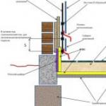 Options for insulating the foundation of a wooden house from the outside
 Why are there cold glasses in warm plastic windows?
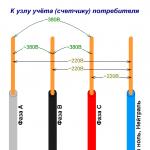 How does three-phase voltage differ from single-phase? Method of using three phases
 Imitation wood inlay
 The best way to sow a garden in the fall after harvesting. The best way to sow a garden for the winter against weeds.
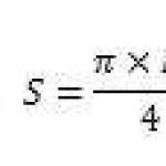 Online calculator for calculating cable cross-section by power