High power channel reactor. High-power channel reactor Metal structure of scheme “C”
Disadvantages of the RBMK-1000 Reactor:
A large number of pipelines and various auxiliary subsystems, which requires a large number of highly qualified personnel;
The need for channel-by-channel flow control, which may lead to accidents associated with the cessation of coolant flow through the channel;
A higher load on operating personnel compared to VVER, associated with the large size of the core and constant fuel refueling in the channels.
Positive vapor coefficient of reactivity. During reactor operation, water is pumped through the core to be used as a coolant. Inside the reactor it boils, partially turning into steam. The reactor had a positive steam coefficient of reactivity, i.e. the more steam, the greater the power released due to nuclear reactions. At the low power at which the power unit operated during the experiment, the effect of the positive vapor coefficient was not compensated by other phenomena affecting reactivity, and the reactor had a positive power coefficient of reactivity.
This means that there was a positive feedback - an increase in power caused processes in the core that led to an even greater increase in power. This made the reactor unstable and dangerous. In addition, operators were not informed that positive feedback could occur at low powers. "End Effect"
Even more dangerous was an error in the design of the control rods. To control the power of the nuclear reaction, rods containing a substance that absorbs neutrons are introduced into the core. When the rod is removed from the core, water remains in the channel, which also absorbs neutrons. In order to eliminate the undesirable influence of this water, displacers made of non-absorbing material (graphite) were placed in the RBMK under the rods.
But with the rod fully raised, a column of water 1.5 meters high remained under the displacer. When the rod moves from the upper position, the absorber enters the upper part of the zone and introduces negative reactivity, and in the lower part of the channel the graphite displacer replaces water and introduces positive reactivity. At the time of the accident, the neutron field had a dip in the middle of the core and two maxima - in its upper and lower parts.
With such a field distribution, the total reactivity introduced by the rods was positive during the first three seconds of movement. This is the so-called “end effect”, due to which the activation of the emergency protection in the first seconds increased the power, instead of immediately stopping the reactor. (The end effect in RBMK is a phenomenon consisting of a short-term increase in the reactivity of a nuclear reactor (instead of the expected decrease), observed on RBMK-1000 reactors when lowering the control and protection system (CPS) rods from the highest (or close to it) position. The effect was caused by poor rod design.
Designs of channels of uranium-graphite reactors of nuclear power plants
Fuel-generating part of the RBMK-1000 channel
(Fig. 2.31) consists of two fuel assemblies, a supporting central rod, a shank, a rod, and a tip. The fuel assembly is assembled from 18 rod-type fuel rods with a diameter of 13.5x0.9 mm, a frame and fasteners; FAs are interchangeable. The frame consists of a central pipe on which one end and ten spacer grilles are fixed. Spacer grids serve to ensure the required
location of fuel elements in the cross section of the fuel assembly and are mounted in the central tube. The fastening of the spacer grids allows them to move along the axis by a distance of 3.5 m during thermal expansion of the fuel elements. The outermost spacer grid is mounted on a key to increase rigidity against torsion of the beam.
The spacer grid is a honeycomb structure and is assembled from a central one, an intermediate pole, twelve peripheral cells and a rim, connected to each other by spot welding. The rim is provided with spacer projections.
Rice. 2.31. FA RBMK-1000:
1 - suspension; 2 - adapter; 3 - shank; 4 - fuel rod; 5 - supporting rod; 6 - bushing; 7 - tip; 8 - nut
The central tube of the fuel assembly at the end has a rectangular cut of half the diameter for joining the fuel assemblies to each other in the channel. This ensures the necessary alignment of the fuel rods of the two fuel assemblies and prevents their rotation relative to each other.
Fuel elements are rigidly fixed in the end grids of the fuel assembly (at the upper and lower boundaries of the core), and when the reactor is operating, the gap in the center of the core is selected due to thermal expansion. Reducing the distance between fuel rods in the center of the core reduces the heat surge and reduces the temperature of the fuel and structural material in the fuel rod plug zone. The use of two fuel assemblies at the height of the core allows each assembly to operate in the zone of both maximum and minimum energy release in height.
All parts of the fuel assembly except the rod and spacer grids are made of zirconium alloy. The rod, which serves to connect the assembly with the suspension, and the spacer grids are made of X18N10T stainless steel.
An analysis of the thermal-hydraulic and strength characteristics of the RBMK-YOO reactor revealed the available reserves for increasing the power of the installation. An increase in the critical power of the process channel, i.e., the power at which a heat transfer crisis occurs on the surface of the fuel elements, accompanied by an unacceptable increase in the temperature of the zirconium cladding, was achieved by introducing heat transfer intensifiers into the fuel assembly. The use of intensifier grids with axial swirl of the coolant flow made it possible to increase the capacity of the RBMK-1000 process channel by 1.5 times. The design of the RBMK-1500 fuel assembly differs from the design of the RBMK-1000 fuel assembly in that spacer intensifier grids are used in the upper fuel assembly; otherwise, the design of the fuel assembly has no fundamental differences. Maintaining the resistance of the circulation circuit is achieved by reducing the coolant flow.
An increase in the power of the fuel assembly causes a corresponding increase in the linear power of the fuel elements to 550 W/cm. Domestic and foreign experience shows that this level of linear power is not the limit. At a number of US stations, the maximum linear powers are 570-610 W/cm.
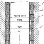
For installation and replacement of the housing of the technological channel during operation, as well as for organizing reliable heat removal for the graphite masonry to the channel, there are “hard contact” rings on its middle part (Fig. 2.32). Split rings 20 mm high are placed along the height of the channel close to each other in such a way that each adjacent ring has reliable contact along the cylindrical surface either with the channel pipe or with the inner surface of the graphite masonry block, as well as at the end with each other. The minimum permissible gaps channel-ring and ring-block are determined from the condition that the channel is not jammed in the masonry as a result of radiation shrinkage of graphite and an increase in the diameter of the channel as a result
creep of pipe material. A slight increase in the gaps will lead to a deterioration in heat removal from the graphite of the masonry. Several bushings are welded on the upper part of the channel body, designed to improve heat removal from the metal structures of the reactor to ensure radiation safety and create technological bases for the manufacture of the channel body.

Rice. 2.32. Installation of a technological channel in graphite masonry:
1- pipe (Zr+2.5% Nb alloy); 2 - outer graphite ring; 3 - inner graphite ring; 4 - graphite masonry
As already noted, zirconium alloys are used mainly for the manufacture of reactor core elements, which take full advantage of their specific properties: neutron
“transparency”, heat resistance, corrosion and radiation resistance, etc. For the manufacture of other parts of the reactor, a cheaper material is used - stainless steel. The combination of these materials is determined by the design requirements, as well as economic considerations regarding materials and technology. The difference in physical, mechanical and technological properties of zirconium alloys and steels causes the problem of their connection.
In industrial reactors, it is known to connect steel with zirconium alloys mechanically, for example, in the Canadian Pickering-2, -3 and -4 reactors, the connection of channel pipes made of zirconium alloy with end fittings made of tempered stainless steel (Fig. 2.33) was made using rolling. However, such compounds work satisfactorily at temperatures of 200-250 °C. Joints between steel and zirconium by fusion welding (argon-arc) and solid-phase welding were studied abroad. Argon-arc welding is carried out at higher temperatures than solid-phase welding, which leads to the formation of layers of brittle intermetallic compounds in the joint zone, which negatively affect the mechanical and corrosion properties of the weld. Among the methods being studied for joining zirconium alloys with steel in the solid phase are explosion welding, joint forging, stamping, pressure welding, joint pressing, resistance brazing, friction welding, etc.
However, all these connections are not applicable for the pipes of the process channel of the RBMK reactor, since all of them are intended
to work under other parameters, and they cannot provide the required density and strength.
The middle zirconium part of the RBMK channel, located in the reactor core, is connected to the stainless steel end assemblies using special steel-zirconium adapters. Steel-zirconium adapters are produced by diffusion welding.
Welding is carried out in a vacuum chamber as a result of strong pressing of parts made of zirconium alloy and stainless steel heated to a high temperature against each other. After mechanical processing, an adapter is obtained, one end of which is a zirconium alloy, the other is stainless steel. To reduce the stresses arising in a connection with a large difference in the linear expansion coefficients of zirconium alloy (a = 5.6 * 10 -6 1/°C) and steel 0Х18Н10Т (a = 17.2 * 10 -6 1/°C), a bandage made of bimetallic hot-pressed pipes is used (steel grade 0Х18Н10Т + steel grade 1Х17Н2) (a=11*10 -6 1/°С).
The connection of the adapter with a zirconium pipe with an outer diameter of 88 and a wall thickness of 4 mm is carried out by electron beam welding. The welds are subject to the same requirements for strength and corrosion properties as the main pipe. The developed modes of electron beam welding, methods and modes of mechanical and thermal treatment of welds and heat-affected zones made it possible to obtain reliable vacuum-tight steel-zirconium welded joints.
In the core of the RBMK-1000 and RBMK-1500 reactors with a square lattice pitch of 250 mm, there are 1693 and 1661 technological channels, respectively, vertically penetrating the seven-meter thickness of the graphite moderator assembled from blocks. The fuel assemblies are located in the supporting pipe of each channel. To a channel pipe Ø 80×4 mm made of Zr = 2.5% Nb alloy in a re-crystallized state, tips made of OKH18N10T steel are attached on both sides by diffusion welding, allowing each channel to be tightly connected to the coolant collector. The coolant - water under a pressure of 8.0 MPa (8.7 MPa in the case of RBMK-1500) is supplied into the channel from below, and saturated steam is discharged through a side fitting in the upper part of the channel at a pressure of 7.3 MPa (7.5 MPa in the case of RBMK -1500). This design of the channel makes it possible, using a reloading machine, to easily load and reload fuel assemblies, including in an operating reactor, two or three pieces every day, according to the operating regulations. To improve heat removal from the graphite masonry, graphite rings are put on the channel pipe, filling the gas gap between the masonry and the channel.
A cassette is essentially loaded into the channel of the RBMK-1000 reactor, consisting of two separate fuel assemblies, located one above the other, connected into a single whole by a hollow supporting rod made of Zr = 2.5% Nb alloy (Ø 15 × 1.25 mm) and attached to the top partly through an adapter to a stainless steel pendant having a gripping device for transportation. In the cavity of the supporting rod, in a separate tubular shell made of zirconium alloy, energy release monitoring sensors or additional neutron absorbers are located, which serve to level out the energy release in the reactor core.
Each upper and lower fuel assembly is formed by a parallel bundle of 18 fuel rod rods, located in cross section along two concentric circles with a fixed radius pitch, which creates a stable heat removal throughout the entire service life of the fuel rods. Fixation of fuel elements is ensured by a frame formed by a supporting central rod and ten spacer grids, evenly spaced along the height of each fuel assembly and holding each fuel element of the bundle in the working openings-cells. Spacer grids are assembled from individual shaped cells, welded together at points and fastened externally with a rim. Each cell has internal protrusions 0.1-0.2 mm long: four in the cells of the outer row and five in the cells of the inner row of fuel rods, firmly, with tension, fixing the fuel rods passed through the cells. This prevents radial movements of fuel elements in the cells, which can be excited by vibration of the structure under the influence of turbulent coolant flow. In this way, the occurrence of fetting corrosion in places where the fuel element cladding touches the metal of the cells is eliminated. The gratings are made of stainless austenitic steel (work is underway to replace the material with a zirconium alloy). The spacer grids have freedom of movement along with the support rod fuel rod bundle, but rotation of the grid relative to the rod axis is excluded.
The fuel rods are attached at one end to the supporting grid using ring locks, crimped into the cutouts of the shaped tips. The other ends of the fuel rods remain free. The supporting grid is an end one, it is rigidly attached to the axial half of the supporting rod. The opposite ends of the supporting rods are cut off with a shoulder of half the diameter, which makes it possible to rigidly close them with a bushing, eliminating any mutual movement, and form a single structure of two fuel assemblies. In this case, between the two bundles of fuel rods in the middle part of the cassette there remains an initial compensating gap, the size of which (about 20 mm) ensures non-closing of the bundles of fuel rods in the process of axial thermal expansion, bundles, thermal “ratchet” and counter radiation growth of the fuel rod cladding. The assembly of fuel assemblies is carried out so that the intra-fuel gas collectors are adjacent to the supporting grids and are located on the border of the reactor core, i.e. in the lower part of the lower fuel assembly and in the upper part of the upper fuel assembly. Each assembly of two fuel assemblies contains 36 fuel rods, their number in the entire core is about 60,000. The total length of the entire fuel assembly with suspension is about 10 m, each fuel assembly is about 3.65 m. The mass of two fuel assemblies is 185 kg, of which 130 kg is uranium dioxide 2.4% enriched with 235U.
The coolant entering the technological channel in a single-phase state moves upward at a speed of 4-7 m/s, depending on the profiling of the coolant flow rate along the radius of the reactor core. In the economizer section of the channel (at a level of about 2.5 m from the entrance to the lower fuel assembly), the coolant is heated to saturation temperature. Above this region, developed boiling occurs and a two-phase state is achieved with a maximum mass vapor content at the outlet of the channel of up to 27% (the average value for the core is 14.5%) and a maximum movement speed of up to 20 m/s. The thermal power of the most intense channel is 3000 kW with a fuel burnup of 18000 MW*day/t U (average value for the core). The duration of stay of fuel assemblies in the reactor core is 3 years.
The assembly of the fuel assemblies of the RBMK-1500 reactor differs from the assembly of the fuel assemblies of the RBMK-1000 reactor by the use in the frame of the upper fuel assembly in the region of the two-phase state of the coolant of special spacer grids located through one and having a number of coolant flow reflectors along the inner surface of the mounting rim, ensuring its forced organized rotation, and consequently, intensification of heat removal practically while maintaining the parameters of the coolant at the entrance to the channel. This solution made it possible to increase the energy release in the RBMK-1500 reactor by one and a half times, and to increase the thermal power of the reactor to 4800 MW with a maximum mass vapor content of the coolant at the exit from the reactor core, reaching 40% (the average value for the core is 30%), its speed of movement 25 m/s and a stable margin before the heat removal crisis. The enrichment of uranium dioxide in 235U in RBMK-1500 fuel rods is 2%.
General structure of the RBMK-1000 reactor
The “heart” of a nuclear power plant is a reactor, in the core of which a chain reaction of fission of uranium nuclei is maintained. RBMK is a channel water-graphite reactor using slow (thermal) neutrons. The main coolant in it is water, and the neutron moderator is the graphite masonry of the reactor. The masonry is composed of 2488 vertical graphite columns, with a base of 250x250 mm and an internal hole with a diameter of 114 mm. 1661 columns are intended for installation of fuel channels in them, 211 - for the control and protection system channels of the reactor, and the rest are side reflectors.The reactor is single-circuit, with boiling coolant in the channels and direct supply of saturated steam to the turbines.

Core, fuel rods and fuel cassettes
The fuel in the RBMK is uranium dioxide-235 U0 2, the degree of fuel enrichment according to U-235 is 2.0 - 2.4%. Structurally, the fuel is located in fuel elements (fuel elements), which are zirconium alloy rods filled with sintered uranium dioxide pellets. The height of the fuel element is approximately 3.5 m, diameter 13.5 mm. Fuel rods are packaged into fuel assemblies (FA), containing 18 fuel rods each. Two fuel assemblies connected in series form a fuel cassette, the height of which is 7 m.Water is supplied to the channels from below, washes the fuel rods and heats up, and part of it turns into steam. The resulting steam-water mixture is removed from the upper part of the channel. To regulate the water flow, shut-off and control valves are provided at the inlet of each channel.
In total, the core diameter is ~12 m, the height is ~7 m. It contains about 200 tons of uranium-235.
CPS
The control rods are designed to regulate the radial field of energy release (PC), automatic power control (AP), rapid shutdown of the reactor (A3) and control of the altitude field of energy release (USP), and the USP rods with a length of 3050 mm are removed from the core downwards, and all the rest with a length of 5120 mm, up.To monitor the energy distribution along the height of the core, 12 channels with seven-section detectors are provided, which are installed evenly in the central part of the reactor outside the network of fuel channels and control rods. The energy distribution along the radius of the core is monitored using detectors installed in the central tubes of the fuel assembly in 117 fuel channels. At the joints of the graphite columns of the reactor masonry, 20 vertical holes with a diameter of 45 mm are provided, in which three-zone thermometers are installed to monitor the graphite temperature.
The reactor is controlled by rods evenly distributed throughout the reactor containing a neutron-absorbing element - boron. The rods are moved by individual servos in special channels, the design of which is similar to technological ones. The rods have their own water cooling circuit with a temperature of 40-70°C. The use of rods of various designs makes it possible to regulate the energy release throughout the entire volume of the reactor and quickly shut it down if necessary.
There are 24 AZ (emergency protection) rods in the RBMK. Automatic control rods - 12 pieces. There are 12 local automatic control rods, 131 manual control rods, and 32 shortened absorber rods (USP).

1. Core 2. Steam-water pipelines 3. Drum-separator 4. Main circulation pumps 5. Dispensing group manifolds 6. Water pipelines 7. Upper biological protection 8. Unloading and loading machine 9. Lower biological protection.
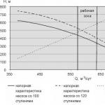
Multiple forced circulation circuit
This is a heat removal circuit from the reactor core. The main movement of water in it is provided by the main circulation pumps (MCP). In total, there are 8 main circulation pumps in the circuit, divided into 2 groups. One pump from each group is a reserve pump. The capacity of the main circulation pump is 8000 m 3 /h, the pressure is 200 m of water column, the engine power is 5.5 MW, the pump type is centrifugal, the input voltage is 6000 V.
In addition to the main circulation pump, there are feed pumps, condensate pumps and safety system pumps.
Turbine
In a turbine, the working fluid - saturated steam - expands and does work. The RBMK-1000 reactor supplies steam to 2 turbines of 500 MW each. In turn, each turbine consists of one high-pressure cylinder and four low-pressure cylinders.At the turbine inlet the pressure is about 60 atmospheres; at the turbine outlet the steam is at a pressure less than atmospheric. The expansion of steam leads to the fact that the flow area of the channel must increase; for this, the height of the blades as the steam moves in the turbine increases from stage to stage. Since steam enters the turbine saturated, expanding in the turbine, it quickly becomes moistened. The maximum permissible moisture content of steam should usually not exceed 8-12% in order to avoid intense erosive wear of the blade apparatus by water drops and a decrease in efficiency.
When the maximum humidity is reached, all steam is removed from the high-pressure cylinder and passed through a separator - steam heater (SPP), where it is dried and heated. To heat the main steam to saturation temperature, steam from the first turbine extraction is used, live steam (steam from the separator drum) is used for superheating, and the heating steam drains into the deaerator.
After the separator - steam heater, the steam enters the low pressure cylinder. Here, during the expansion process, the steam is again moistened to the maximum permissible humidity and enters the condenser (K). The desire to get as much work as possible from every kilogram of steam and thereby increase efficiency forces us to maintain the deepest possible vacuum in the condenser. In this regard, the condenser and most of the low-pressure cylinder of the turbine are under vacuum.
The turbine has seven steam extractions, the first is used in the separator-superheater to heat the main steam to saturation temperature, the second extraction is used to heat water in the deaerator, and extractions 3 – 7 are used to heat the main condensate flow in, respectively, PND-5 - PND- 1 (low pressure heaters).
Fuel cassettes
Fuel rods and fuel assemblies are subject to high reliability requirements throughout their entire service life. The complexity of their implementation is aggravated by the fact that the length of the channel is 7000 mm with a relatively small diameter, and at the same time, machine overload of the cassettes must be ensured both when the reactor is stopped and when the reactor is running.
|
||||||||||||||||||||||||||||||||||||||||||
Loading and unloading machine (RZM)
A distinctive feature of the RBMK is the ability to reload fuel cassettes without stopping the reactor at rated power. In fact, this is a routine operation and is performed almost daily.The installation of the machine over the corresponding channel is carried out according to coordinates, and precise guidance to the channel using an optical-television system, through which you can observe the head of the channel plug, or using a contact system in which a signal is generated when the detector touches the side surface of the top of the channel riser.
The REM has a sealed case-suit surrounded by biological protection (container), equipped with a rotary magazine with four slots for fuel assemblies and other devices. The suit is equipped with special mechanisms for performing overload work.
When reloading fuel, the suit is compacted along the outer surface of the channel riser, and a water pressure is created in it equal to the coolant pressure in the channels. In this state, the stopper plug is released, the spent fuel assembly with suspension is removed, a new fuel assembly is installed and the plug is sealed. During all these operations, water from the rare earth metal enters the upper part of the channel and, mixing with the main coolant, is removed from the channel through the outlet pipeline. Thus, when reloading fuel, continuous circulation of the coolant is ensured through the overloaded channel, while water from the channel does not enter the rare earth metal.

(RBMK listen)) - a series of nuclear power reactors developed in the Soviet Union. This reactor is a channel, uranium-graphite (graphite-water moderator), boiling-type, thermal neutron reactor; designed to produce saturated steam with a pressure of 70 kg/cm?. The coolant is boiling water.
Chief designer of the reactor plant: NIKIET, Academician Dollezhal N.A.
Scientific director of the project: IAE im. I. V. Kurchatova, Academician Alexandrov A. P.
General designer (LNPP): GSPI-11 (VNIPIET), Gutov A. I.
Chief designer of the turbine unit: KhTGZ, "Turboatom", Kosyak Yu. F.
Metal structure developer: TsNIIPSK, Melnikov N. I.
Leading materials science organization:“Prometheus”, Kopyrin G. I.
Designer and manufacturer of electromechanical equipment for control and control systems, WHO: Design Bureau of the Bolshevik Plant, Klaas Yu. G.
At the moment, the series of these reactors includes three generations.
Main reactor of the series- Units 1 and 2 of the Leningrad NPP.
1 History of creation and operation 2 Characteristics of RBMK 3 Construction 3.1 RBMK-1000 3.2 Unit 5 of Kursk NPP (3rd generation RBMK-1000) 3.3 RBMK-1500 3.4 RBMK-2000, RBMK-3600 RBMKP-2400, RBMKP-4800 (former projects) 3.4.1 RBMK-2000, RBMK-3600 3.4.2 RBMKP-2400, RBMKP-4800 3.5 MKER (modern projects) 4 Advantages 5 Disadvantages 6 Operating practice |
History of creation and operation
Central hall of RBMK-1500
(Ignalina NPP)
Reactor The world's first nuclear power plant was a uranium-graphite channel reactor with water coolant AM-1 (Atom Mirny), installed at the Obninsk NPP (1954). The development of uranium-graphite reactor technologies was carried out on industrial reactors, including “dual” purpose reactors (which produced electricity in addition to “military” isotopes): A (1948), AI (PO Mayak), I-1 (1955 year), EI-2 (1958), ADE series (Siberian Chemical Plant). Since the 1960s, the USSR began developing purely power reactors such as the future RBMK. Some design solutions were tested on experimental power reactors "Atom Mirny Bolshoi": AMB-1 (1964) and AMB-2 (1967), installed at the Beloyarsk NPP.
The development of RBMK reactors themselves began in the mid-60s and relied largely on extensive and successful experience in the design and construction of industrial uranium-graphite reactors. The main advantages of the reactor plant were seen by the creators as:
maximum use of experience from uranium-graphite reactors;
well-established connections between factories, established production of basic equipment;
the state of industry and the construction industry of the USSR;
promising neutronics characteristics (low fuel enrichment).
In general, the design features of the reactor repeated the experience of previous uranium-graphite reactors. The fuel channel, assemblies of fuel elements made of new structural materials - zirconium alloys, and with a new form of fuel - metallic uranium was replaced by its dioxide, as well as coolant parameters, became new. The reactor was initially designed as a single-purpose reactor - for the production of electrical and thermal energy.
Work on the project began at the Institute of Atomic Energy (RRC KI) and NII-8 (NIKIET) in 1964. In 1965, the project was named B-190, and its construction was entrusted to the design bureau of the Bolshevik plant. In 1966, by decision of the ministerial NTS, work on the project was entrusted to NII-8 (NIKIET), led by Dollezhal.
On April 15, 1966, the head of the Ministry of Medium Machine Building, E.P. Slavsky, signed a task for the design of the Leningrad Nuclear Power Plant, 70 km in a straight line west of Leningrad, 4 km from the village of Sosnovy Bor. At the beginning of September 1966, the design task was completed.
On November 29, 1966, the Council of Ministers of the USSR adopted Resolution No. 800-252 on the construction of the first stage of the Leningrad NPP, and determined the organizational structure and cooperation of enterprises for the development of the design and construction of the nuclear power plant.
The first power unit with a RBMK-1000 type reactor was launched in 1973 at the Leningrad NPP.
During the construction of the first nuclear power plants in our country, there was an opinion that a nuclear power plant is a reliable source of energy, and possible failures and accidents are unlikely, or even hypothetical events. In addition, the first units were built within the medium engineering system and were intended to be operated by organizations of this ministry. At the time of development, safety rules were either absent or imperfect. For this reason, the first power reactors of the RBMK-1000 and VVER-440 series did not have a sufficient number of safety systems, which subsequently required a serious modernization of such power units. In particular, in the initial design of the first two RBMK-1000 units of the Leningrad NPP there were no hydrocylinders for the emergency reactor cooling system (ERCS), the number of emergency pumps was insufficient, there were no check valves (OC) on the distribution group manifolds (RGK), etc. In the future , during modernization, all these shortcomings were eliminated.
Further construction of RBMK units was supposed to be carried out for the needs of the USSR Ministry of Energy. Taking into account the lesser experience of the Ministry of Energy with nuclear power plants, significant changes were made to the project to increase the safety of power units. In addition, changes were made to take into account the experience of the first RBMKs. Among other things, ECCS hydraulic cylinders were used, 5 pumps began to perform the function of ECCS emergency electric pumps, check valves were used in the RGK, and other improvements were made. Based on these projects, power units 1 and 2 of the Kursk NPP and 1 and 2 of the Chernobyl NPP were built. At this stage, the construction of the first generation RBMK-1000 power units (6 power units) was completed.
Further improvement of nuclear power plants with RBMK began with the development of projects for the second stage of the Leningrad NPP (power units 3, 4). The main reason for finalizing the project was the tightening of safety rules. In particular, a balloon ECCS system, a long-term cooling ECCS system, represented by 4 emergency pumps, was introduced. The accident localization system was not represented by a bubbler tank, as before, but by an accident localization tower capable of accumulating and effectively preventing the release of radioactivity in accidents involving damage to reactor pipelines. Other changes were made. The main feature of power units 3 and 4 of the Leningrad NPP was the technical solution to locate the RGC at an altitude higher than the altitude of the core. This made it possible, in the event of an emergency water supply to the RGC, to have a guaranteed flooding of the core with water. This decision was not applied subsequently.
After the construction of power units 3 and 4 of the Leningrad NPP, which is under the jurisdiction of the Ministry of Medium Engineering, the design of RBMK-1000 reactors began for the needs of the USSR Ministry of Energy. As noted above, when developing a nuclear power plant for the Ministry of Energy, additional changes were made to the project designed to increase the reliability and safety of the nuclear power plant, as well as increase its economic potential. In particular, when finalizing the second stages of the RBMK, a drum separator (DS) of larger diameter was used (the internal diameter was increased to 2.6 m), a three-channel ECCS system was introduced, the first two channels of which were supplied with water from hydraulic cylinders, the third - from feed pumps. The number of emergency water supply pumps to the reactor was increased to 9 and other changes were made that significantly increased the safety of the power unit (fundamentally, the level of performance of the ECCS satisfied not only the documents in force at the time of the design of the nuclear power plant, but also, in many respects, modern requirements). The capabilities of the accident localization system, which was designed to counter an accident caused by a guillotine rupture of a pipeline of maximum diameter (pressure manifold of the main circulation pumps (MCP) DN 900), have significantly increased. Instead of the bubbler tanks of the first stages of the RBMK and the localization towers of Units 3 and 4 of the Leningrad NPP, the second generation RBMK MINENERGO used two-story localizer pools, which significantly increased the capabilities of the accident localization system (ALS). The lack of containment was compensated by the strategy of using a system of tight-durable boxes (TPB), in which the pipelines of the multiple forced circulation circuit of the coolant were located. The design of the PPB and the thickness of the walls were calculated based on the condition of maintaining the integrity of the premises in the event of a rupture of the equipment located in it (up to the pressure manifold of the MCP DN 900 mm). The PPB did not cover BS and steam-water communications. Also, during the construction of nuclear power plants, reactor compartments were built as a double block, which means that the reactors of two power units are essentially in one building (unlike previous nuclear power plants with RBMK, in which each reactor was located in a separate building). This is how the second generation RBMK-1000 reactors were built: power units 3 and 4 of the Kursk NPP, 3 and 4 of the Chernobyl NPP, 1 and 2 of the Smolensk NPP (total, together with units 3 and 4 of the Leningrad NPP, 8 power units).
A total of 17 RBMK power units have been commissioned. The payback period for serial units of the second generation was 4-5 years.
The contribution of nuclear power plants with RBMK reactors to the total electricity generation by all nuclear power plants in Russia is about 50%.
Before the accident at the Chernobyl nuclear power plant in the USSR, there were extensive plans to build such reactors, but after the accident, plans to build RBMK power units at new sites were curtailed. After 1986, two RBMK reactors were launched: RBMK-1000 at Smolensk NPP (1990) and RBMK-1500 at Ignalina NPP (1987). Another RBMK-1000 reactor of the 5th block of the Kursk NPP is at the stage of completion (~70-80% readiness). After the accident at the Chernobyl nuclear power plant, additional research and modernization were carried out. Currently, RBMK reactors are not inferior in safety and economic indicators to domestic and foreign nuclear power plants of the same period of construction. To date, the acceptable level of RBMK safety has been confirmed at the national level, as well as by international examinations.
The development of the concept of a channel uranium-graphite reactor is carried out in the MKER projects - Multi-loop Channel Energy Reactor.
Characteristics of RBMK
| Characteristic | RBMK-1000 | RBMK-1500 | RBMKP-2400 (project) |
MKER-1500 (project) |
|---|---|---|---|---|
| Reactor thermal power, MW | 3200 | 4800 | 5400 | 4250 |
| Electric power of the unit, MW | 1000 | 1500 | 2000 | 1500 |
| Block efficiency, % | 31,3 | 31,3 | 37,0 | 35,2 |
| Steam pressure in front of the turbine, atm | 65 | 65 | 65 | 65? |
| Steam temperature in front of the turbine, °C | 280 | 280 | 450 | |
| Core dimensions, m: | ||||
| height | 7 | 7 | 7,05 | 7 |
| diameter (width? length) | 11,8 | 11,8 | 7,05?25,38 | 14 | 192 | 189 | 220 |
| Enrichment, % 235U | ||||
| evaporation channel | 2,6-3,0 | 2,6-2,8 | 1,8 | 2-3,2 |
| overheating channel | - | - | 2,2 | - |
| Number of channels: | ||||
| evaporative | 1693-1661 | 1661 | 1920 | 1824 |
| overheating | - | - | 960 | - |
| Average burnup, MW day/kg: | ||||
| in the evaporation channel | 22,5 | 25,4 | 20,2 | 30-45 |
| in the superheating channel | - | - | 18,9 | - |
| Dimensions of the fuel rod shell (diameter? thickness), mm: | ||||
| evaporation channel | 13,5?0,9 | 13,5?0,9 | 13,5?0.9 | - |
| overheating channel | - | - | 10?0,3 | - |
| Material of fuel rod shells: | ||||
| evaporation channel | Nb | Zr + 2.5% Nb | Zr + 2.5% Nb | - |
| overheating channel | - | - | Stainless steel steel | - |
Design
NPP power unit diagram
with RBMK type reactor
One of the goals in the development of the RBMK reactor was to improve the fuel cycle. The solution to this problem is associated with the development of structural materials that weakly absorb neutrons and differ little in their mechanical properties from stainless steel. Reducing neutron absorption in structural materials makes it possible to use cheaper nuclear fuel with low uranium enrichment (1.8% according to the original design).
RBMK-1000
NPP power unit diagramwith RBMK reactor Fuel assembly of RBMK reactor:
1 - spacer
2 - TVEL shell
3 - nuclear fuel pellets
The basis of the RBMK-1000 core is a graphite cylinder 7 m high and 11.8 m in diameter, made up of smaller blocks, which acts as a moderator. The graphite is pierced with a large number of vertical holes, through each of which passes a pressure pipe (also called technological channel(TK)). The central part of the pressure pipe, located in the core, is made of zirconium alloy (Zr + 2.5% Nb), which has high mechanical and corrosion properties, the upper and lower parts of the pressure pipe are made of stainless steel. The zirconium and steel parts of the pressure pipe are connected by welded adapters.
When designing RBMK power units, due to the imperfection of calculation methods, the channel grid spacing was chosen to be non-optimal. As a result, the reactor was somewhat overslowed, which led to positive values of the vapor coefficient of reactivity in the working region, exceeding the fraction of delayed neutrons. Before the Chernobyl accident, the method used to calculate the steam coefficient of reactivity curve (BMP program) showed that despite the positive RCC in the area of working steam content, as steam content increases, this value changes sign, so that the dehydration effect was negative. Accordingly, the composition and performance of security systems was designed taking this characteristic into account. However, as it turned out after the accident at the Chernobyl nuclear power plant, the calculated value of the steam coefficient of reactivity in areas with high steam content was obtained incorrectly: instead of negative, it turned out to be positive. To change the vapor coefficient of reactivity, a number of measures were carried out, including the installation of additional absorbers in some channels instead of fuel. Subsequently, to improve the economic performance of power units with RBMKs, additional absorbers were removed; in order to achieve the specified neutron-physical characteristics, higher enrichment fuel with an additional absorber (erbium oxide) began to be used.
Each fuel channel has a cassette made up of two fuel assemblies(TVS) - lower and upper. Each assembly includes 18 fuel rods. The fuel rod shell is filled with uranium dioxide pellets. According to the original design, the enrichment for uranium 235 was 1.8%, but as experience in operating the RBMK accumulated, it turned out to be advisable to increase the enrichment. Increased enrichment in combination with the use of a burnable absorber in the fuel made it possible to increase the controllability of the reactor, improve safety and improve its economic performance. Currently, a transition to fuel with 3.0% enrichment is underway.
The RBMK reactor operates according to a single-circuit design. The coolant circulates in a multiple forced circulation circuit (MCPC). In the core, the water cooling the fuel elements partially evaporates and the resulting steam-water mixture enters the separator drums. In drum separators, steam is separated and supplied to the turbine unit. The remaining water is mixed with feed water and, using the main circulation pumps (MCP), is supplied to the reactor core. The separated saturated steam (temperature ~284 °C) under a pressure of 70-65 kgf/cm2 is supplied to two turbogenerators with an electrical power of 500 MW each. The exhaust steam is condensed, after which, after passing through regenerative heaters and a deaerator, it is supplied using feed pumps (FEN) to the CMP.
RBMK-1000 reactors are installed at the Leningrad NPP, Kursk NPP, Chernobyl NPP, and Smolensk NPP.
5th power unit of Kursk NPP
(RBMK-1000 3rd generation)
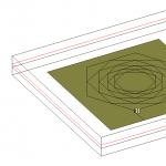
At the 5th unit of the Kursk NPP under construction (currently 70–80% complete), in addition to other measures to improve the RBMK, the design of the reactor’s graphite lining, which has an octagonal cross-section, is fundamentally new. By reducing the volume of graphite, the ratio of the fuel fraction to the moderator fraction changes, which has a significant impact on the vapor coefficient of reactivity. As a result, with a guaranteed negative vapor coefficient of reactivity, the RBMK-1000 reactor of the 5th unit of the Kursk NPP operates with minimal ORM, which further increases its economic efficiency. In the future, it is possible to consider the issue of increasing fuel enrichment for the RBMK 5th unit of the Kursk NPP, which will further improve its economic performance while maintaining a high level of safety.
This unit formally belongs to the 3rd generation of RBMK (the 3rd unit of the Smolensk NPP also belongs to it), but, judging by the depth of the changes made, it would be more correct to classify it as the “3+” generation.
RBMK-1500
In the RBMK-1500, the power is increased by increasing the specific energy intensity of the core by increasing the power of the fuel complex by 1.5 times while maintaining its design. This is achieved by intensifying heat removal from the fuel rods by using special heat transfer intensifiers (turbulators) in the fuel assemblies in the upper part of both fuel assemblies. All together, this makes it possible to maintain the same dimensions and overall design of the reactor.
RBMK-1500 FA intensifiers should be distinguished from the spacer grids installed on each FA in the amount of 10 pieces, which also contain turbulators.
During operation, it turned out that, due to high unevenness of energy release, periodically occurring increased (peak) powers in individual channels lead to cracking of the fuel rod cladding. For this reason, the power was reduced to 1300 MW.
These reactors are installed at the Ignalina NPP (Lithuania).
RBMK-2000, RBMK-3600
RBMKP-2400, RBMKP-4800
(former projects)
Due to the general design feature of RBMK reactors, in which the core, like cubes, was assembled from a large number of similar elements, the idea of further increasing power suggested itself.
RBMK-2000, RBMK-3600
In project RBMK-2000 the increase in power was planned by increasing the diameter of the fuel channel, the number of fuel rods in the cassette and the pitch of the fuel tube sheet. At the same time, the reactor itself remained the same dimensions.
RBMK-3600 was only a conceptual project, little is known about its design features. It is likely that the issue of increasing the power density was resolved in it, like the RBMK-1500, by intensifying heat removal, without changing the design of its RBMK-2000 base - and, therefore, without increasing the core.
RBMKP-2400, RBMKP-4800
MKER (modern projects)
MKER reactor plants are an evolutionary development of the RBMK generation of reactors. They take into account new, more stringent safety requirements and eliminate the main disadvantages of previous reactors of this type.
The operation of MKER-800 and MKER-1000 is based on the natural circulation of coolant, intensified by water-water injectors. Due to its large size and power, MKER-1500 operates with forced circulation of the coolant, developed by the main circulation pumps. Reactors of the MKER series are equipped with a double protective shell - a containment: the first is steel, the second is reinforced concrete without creating a prestressed structure. The diameter of the containment shell MKER-1500 is 56 meters (corresponding to the diameter of the containment shell of the Bushehr NPP). Due to the good balance of neutrons, MKER reactor plants have a very low consumption of natural uranium (for MKER-1500 it is 16.7 g/MWh(e) - the lowest in the world).
Expected efficiency - 35.2%, service life 50 years, enrichment 2.4%.
Advantages
Reduced, compared to vessel-type VVERs, water pressure in the primary circuit;
Thanks to the channel design, there is no expensive housing;
There are no expensive and complex steam generators;
There are no fundamental restrictions on the size of the core (for example, it can be in the shape of a parallelepiped, as in RBMKP projects);
Independent control and protection system (CPS) circuit;
Wide possibilities for regular monitoring of the condition of core components (for example, process channel pipes) without the need to shut down the reactor, and also
high maintainability;
Easier occurrence (compared to vessel-type VVERs) of accidents caused by depressurization of the circulation circuit, as well as transient conditions caused by equipment failures;
The ability to form optimal neutronic properties of the reactor core (reactivity coefficients) at the design stage;
Insignificant reactivity coefficients based on coolant density (modern RBMK);
Replacement of fuel without shutting down the reactor due to the independence of the channels from each other (in particular, it increases the capacity factor);
Possibility of producing radionuclides for technical and medical purposes, as well as radiation doping of various materials;
Absence (compared to vessel-type VVERs) of the need to use boron regulation;
More uniform and deeper (compared to vessel-type VVER) burnup of nuclear fuel;
Possibility of operating a reactor with a low ORM - operational reactivity margin (modern projects, for example, the fifth power unit of the Kursk NPP under construction);
Cheaper fuel due to lower enrichment, although the fuel load is much higher (the general fuel cycle uses reprocessing of spent fuel from
Channel-by-channel regulation of coolant flow rates through channels, allowing control of the thermal reliability of the core;
Thermal inertia of the core, significantly increasing the reserves before fuel damage during possible accidents;
Independence of the loops of the reactor cooling circuit (in RBMK there are 2 loops), which makes it possible to localize accidents in one loop.
Flaws
A large number of pipelines and various auxiliary subsystems require a large number of highly qualified personnel;
The need for channel-by-channel flow control, which may lead to accidents associated with the cessation of coolant flow through the channel;
Higher load on operating personnel compared to VVER, associated with a large number of components (for example, shut-off and control valves);
Due to the large size of the core and the metal content of the RBMK, a larger amount of activated structural materials remains after decommissioning and requires disposal.
Operating practice
IAEA, PRIS Database.
Cumulative capacity factor for all operating power units:
RBMK - 69.71%; VVER - 71.54%.
Data from the beginning of the block input to 2008.
Russian Federation. Only active blocks.
Accidents at power units with RBMK
The most serious incidents at nuclear power plants with RBMK reactors:
1975 - rupture of one channel at the first block of the Leningrad NPP;
1982 - rupture of one channel at the first block of the Chernobyl nuclear power plant;
1986 - accident with a massive rupture of channels at the fourth unit of the Chernobyl nuclear power plant;
1991 - fire in the turbine room of the second unit of the Chernobyl nuclear power plant;
1992 - rupture of one channel at the third block of the Leningrad NPP;
The 1982 accident was associated with the actions of operational personnel who grossly violated technological regulations.
In the 1986 accident, in addition to personnel violations, the dangerous properties of the RBMK manifested themselves, which significantly influenced the scale of the accident. After the accident, a lot of scientific and technical work was carried out. The measures taken have eradicated such dangerous properties.
The 1991 accident in the turbine room of the second unit of the Chernobyl Nuclear Power Plant was caused by equipment failures independent of the reactor plant. During the accident, due to a fire, the roof of the turbine room collapsed. As a result of the fire and roof collapse, the reactor water supply pipelines were damaged, and the BRU-B steam relief valve was blocked in the open position. Despite the numerous failures of systems and equipment that accompanied the accident, the reactor showed good self-protection properties, which prevented heating and damage to the fuel.
1992 - the rupture of one channel at the third unit of the Leningrad NPP was caused by a valve defect.
Status for 2010
As of 2010, 11 power units with RBMK are in operation at three nuclear power plants: Leningrad, Kursk, and Smolensk. For political reasons (in accordance with Lithuania’s obligations to the European Union), two power units at the Ignalina Nuclear Power Plant and three power units at the Chernobyl Nuclear Power Plant were shut down (another one ceased to exist as a result of the accident). Construction of the third stage of RBMK is underway at the fifth power unit of the Kursk NPP.
List of abbreviations, RBMK terminology
A3 - emergency protection; core
AZM - emergency protection (signal) for excess power
AZRT - emergency protection of a reactor installation according to technological parameters (system)
Gas station - emergency protection (signal) based on the rate of power rise
AR - automatic regulator
ASKRO - automated system for monitoring the radiation situation
NPP - nuclear power plant
BAZ - fast-acting emergency protection
BB - bubbler pool
NIR - side ionization chamber
BOU - block treatment plant
BRU-D - high-speed reducing device with discharge into a deaerator
BRU-K - high-speed reduction device with discharge into the turbine condenser
BS - drum separator
Control room - block control panel
VIC - high altitude ionization chamber
VIUB (SIUB) - leading (senior) unit control engineer
VIUR (SIUR) - leading (senior) reactor control engineer
VIUT (SIUT) - leading (senior) turbine control engineer
GPK - main safety valve
MCP - main circulation pump
DKE (r), (v) - energy release control sensor (radial), (high-altitude)
DP - additional absorber
DREG - diagnostic registration parameters
ZRK - shut-off and control valve
KGO - control of the tightness of the shell (TVELs)
CD - fission chamber
KIUM - installed capacity utilization factor
KMPC - multiple forced circulation circuit
KN - condensate pump
KCTK - integrity monitoring of process channels (system)
LAZ - local emergency protection
LAR - local automatic regulator
IAEA - International Atomic Energy Agency
MPA - maximum design basis accident
NVK - lower water communications
NK - pressure manifold
NSB - block shift supervisor
NSS - station shift supervisor
ORM - operational reactivity reserve (conventional "rods")
OK - check valve
OPB - “General Safety Provisions”
PNY - “Nuclear Safety Rules”
PVK - steam-water communications
PN - feed pump
PPB - dense and durable box
PRISMA - device power measurement program
PEN - electric feed pump
RBMK - high power channel reactor (boiling)
RGK - distribution-group manifold
RZM - loading and unloading machine
RK CPS - working channel of the control and protection system
RP - reactor space
PP - manual regulation
RU - reactor plant
ECCS - emergency reactor cooling system
SB - security systems
SLA - accident localization system
SP - absorber rod
SPIR - purging and cooling system
SRK - stop and control valve
STK - process control system
CPS - control and protection system
SFKRE - system for physical control of energy distribution
SCS "Skala" - centralized control system (SKALA - control system of the Leningrad Atomic plant apparatus)
FA - fuel assembly
TVEL - fuel element
TG - turbogenerator
TK - technology channel
USP - shortened absorber rod (manual)
NF - nuclear fuel
NFC - nuclear fuel cycle
NEU - nuclear power plant
Materials: dic.academic.ru